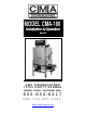
MODEL CMA-180 Installation & Operation Rev 2.03 CMA DISHMACHINES 12700 KNOTT AVENUE GARDEN GROVE, CALIFORNIA 92841 800-854-6417 FAX 714-895-2141 www.cmadishmachines.
Table of Contents CMA-180 1. SPECIFICATIONS................................................................................................. 2 1.1 CMA-180/CMA-180T.................................................................................................................... 2 1.1. CMA-180/CMA-180T.................................................................................................................... 3 2. GETTING STARTED .................................................................
1. Specifications 1.1 Metric Equivalent CMA-180/CMA-180T WATER CONSUMPTION PER RACK .96 GAL. (3.6 L) PER HOUR 52 GAL. (197 L) WASH TIME-SEC 49 49 RINSE TIME-SEC 12 12 61 MIN. 61 MIN. 60 60 WASH TANK CAPACITY 8 GAL. (30.3 L) PUMP CAPACITY 68 GPM (257 LPM) OPERATING CYCLE TOTAL CYCLE OPERATING CAPACITY RACKS PER HOUR (NSF rated) WATER REQUIREMENTS WITHOUT BOOSTER HEATER 180°F (82°C) WITH BOOSTER HEATER 140°F (60°C) WATER INLET ¾” 1.9cm DRAIN CONNECTION 2” 5.
1.1. CMA-180/CMA-180T VOLTS PHASE AMPS 208 1 28/35 240 1 30/38 208 3 20/24 240 3 21/26 ELECTRICAL RATING 208 1 71/78 WITH BOOSTER 240 1 80/88 208 3 45/49 240 3 50/55 ELECTRICAL RATING WITHOUT BOOSTER SHIPPING WEIGHT WITHOUT BOOSTER WITH BOOSTER MODEL CMA-180 INSTALLATION & OPERATION Rev. 2.
2. Getting Started 2.1. Introduction to CMA-180 The CMA-180 is a hot water sanitizing, single rack, door-type dishmachine. It is a stand-alone machine featuring a self-contained booster heater (optional). The only external connections necessary are power supply, water supply, drainpipe, and chemical dispensers. The machine utilizes recirculated wash water and fresh water final rinse. The CMA-180 can be converted both as a straight through and corner with a door handle kit.
2.2. Receiving and Installation Step 1: Remove packaging material. Step 2: Remove service manual and machine legs from inside the wash tank. Step 3: Install legs into dishmachine leg lockets and adjust the feet. Set the machine in place. Level the machine side – to – side and front – to – back. Step 4: It is recommended that a distance of at least eight inches (8”) be between the table scrap sink and the dishmachine. 2.2.1.
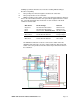
flexibility to permit the machine to be moved for cleaning without having to disconnect any wiring. ii. Run your dispenser wires through the conduit to the control box. iii. Run your probe wires to the control box. iv. With the machine’s power “OFF”, connect your detergent and rinse dispenser wires to the red and blue terminals of the power block supplied inside the control box. The table that follows lists the function of each conductor of the multiconductor electrical cable.
2. Remove the plug from the mixing chamber located by the vacuum breaker on the back of machine; and install the rinse injection fitting (supplied with your dispenser). 3. A 7/8” detergent injection hole is provided in the back of the wash tank. Remove the S.S. plug and install the detergent fitting (supplied with your dispenser). 4. A 7/8” chemical probe hole is provided in the front of the wash tank heater just below hi limit switch.
2.2.4. Exhaust Fan Control MODEL CMA-180 INSTALLATION & OPERATION Rev. 2.
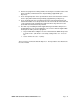
2.2.5. Water Tempering Kit MODEL CMA-180 INSTALLATION & OPERATION Rev. 2.
2.2.6. Installation Checklist Dishmachine checked for concealed damage. Hot water supply is 140° (60°C) Incoming water supply line is ¾”. Incoming water supply is 6 gpm minimum capable at 20 psi flow pressure. Machine circuit breaker is properly sized. Service voltage and phase type are correct to machine data plate. High leg of voltage is connected to L2 (three-phase). Dishmachine is properly ventilated. Floor drain plumbing is installed with air gap. Dishmachine is properly grounded.
2.2.7. Machine Start-Up Procedures 1. Open doors and install the overflow & scrap trap on the right side of the machine. 2. Place the scrap baskets over the wash tanks. 3. Secure the wash & rinse arms and check the free-spin. 4. Open the control cover and select ‘normal” toggle switch position. 5. Adjust the rinse pressure to 20 psi flow pressure using the regulator and the gauge. a. Turn the power switch to the “Off” position. b.
2.2.8. Electrical Requirements The CMA-180 comes standard factory, wired for 3-phase operation. Check the electrical data plate to confirm this. If the account requires 1 phase, refer to “Electrical Requirements”, Section 1-A, for proper wiring instruction for conversion. Also check the wiring diagram to properly wire the terminal power block, tank heater, and booster heater for 1 phase (or 1B diagram below).
3. Wiring Options 3-Phase and 1 Phase Wiring Options Single-Source 220V 3-Phase (20 amp/12 g*) Single-Source 220V 3-Phase (50 amp/8 g*) Single-Source 220V 1-Phase (80 amp/4 g*) (without Booster) Two-Source 220V 1-Phase (50 amp/8 g*) (30 amp/10 g*) Single-Source 220V 1-Phase (30 amp/10 G*) (without booster) *g=gauge DISPENSER HOOK-UP 1. The power signal is 208/230 volts. The power block is labeled inside the control box. Conduit holes for both detergent & rinse are supplied on the control box. 2.
4. Quick service guide MODEL: CMA 180 HIGH TEMP TECHNICAL ISSUE Door magnetic reed switch problem Door mechanical switch problem Pump motor not running Pump motor runs continuous CAUSE Faulty magnetic reed switch SOLUTION Check wire connections inside control box Switch alignment issue Contact factory for new retrofit, corner P/N 00566.10 straight P/N 00566.20 Align switch Switch button broke Replace switch, P/N00562.
5. INITIAL PARTS KIT P/N 1100.17 P/N 00121.18 00200.10 00206.00 00302.19 00304.17 00304.19 00308.17 00308.50 00363.00 00404.85 00405.00 00411.00 00475.00 00501.17 00562.00 00602.00 00631.05 00706.00 00735.00 00738.15 03202.00 03202.00 03408.55 13003.17 13003.50 13304.55 13415.00 13417.47 13417.65 13417.67 13417.85 13463.10 13605.00 00421.90 00421.78 17523.51 DESCRIPTION CMA-180 Drain Stopper O Ring Pump Assy 110/220V 60 Hz (Open) Pump Seal Kit CMA-180 Buna Gasket (#302.
6. Auto-Fill Solid State Timer Pre-selected delay period can be adjusted by turning securely small flat screwdriver. Since the range of this solid state timer is from 6 seconds to 240 seconds, you should adjust delay by small increment. Removal of input power will reset the control. AUTO-FILL SWITCH L2 L1 WASH PUMP CONTACTOR 6 T2 WATER SOLENOID VALVE T1 1 MODEL CMA-180 INSTALLATION & OPERATION Rev. 2.
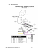
7. Wire Diagram MODEL CMA-180 INSTALLATION & OPERATION Rev. 2.
DETERGENT { L1 L3 GND L3 L2 L1 L2 L1 L3 L2 L1 HEATER CONTACTOR RINSE SIGNAL { BOOSTER HEATER CONTACTOR L2 GROUND WASH PUMP CONTACTOR 8. Wire Diagram for CMA-180 Booster Only T2 T1 T3 T2 T1 T3 T2 T1 PUMP MOTOR HI LIMIT SWITCH 5kW ADJ. THERMOSTAT WASH TANK HEATER 12kW BOOSTER HEATER MODEL CMA-180 INSTALLATION & OPERATION Rev. 2.