CMA Dishmachines 12700 Knott Street Garden Grove, CA 92841 Toll Free: Fax: 1- (800) 854-6417 1- (714) 895-2141 Installation/Operation Manual Undercounter High Temperature Dishwasher Models: UC65e UC65e Machine Serial No. Issue Date: 4.17.09 Manual P/N 0512865 rev.
For future reference, record your dishwasher information in the box below.
Revision History Revision History • The Revision History can contain part number changes, new instructions, or information that was not available at print time. • We reserve the right to make changes to these instructions without notice and without incurring any liability by making the changes.. • Equipment owners may request a revised manual, at no charge, by calling CMA Dishmachines at 1 (800) 854-6417. Revision Date 4.17.
Model Description Model Description UC65e High temperature hot water sanitizing dishwasher with built-in 40°F/22°C rise booster heater.
Table of Contents Table of Contents Model UC65e Undercounter Dishwasher Revision History...................................................................................................................i Model Descriptions...............................................................................................................ii Installation...............................................................................................1 Receiving.......................................................
Blank Page This Page Intentionally Left Blank iv
Installation Receiving NOTE: The installation of your dishwasher must be performed by qualified service personnel. Problems due to improper installation are not covered by the Warranty. 1. Inspect the outside of the dishwasher carton for signs of damage. 2. Remove the carton and inspect the dishwasher for damage. 3. Check for any accessories that may have shipped with your dishwasher. 4. Move the dishwasher near its permanent location.
Installation Electrical Connections WARNING: Electrocution or serious injury may result when working on an energized circuit. Disconnect power at the main breaker or service disconnect switch before working on the circuit. Lock-out and tag the breaker to indicate that work is being performed on the circuit.
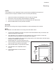
Installation Electrical Connections 1. Refer to the connection diagram on the preceding page and the photo below: 2. Machines require a 3-wire plus ground supply which includes a current carrying neutral. 3. Power connections are made at the Main Terminal Block (MTB). 4. The MTB is located on the left-rear corner of the electrical panel behind the front access panel. (See the illustration on the previous page.
Installation Water Connections Note Plumbing connections must comply with national, local plumbing and sanitary codes. IMPORTANT Make sure that the flexible water supply and drain hoses are not kinked. 1. All models have a 6 ft. flexible hot water fill hose with a 3/4" GHT connector. 2. A 1/2" or larger main incoming supply line should be installed to the dishwasher. 3. A 1/2" or larger shut-off valve should be installed in the water supply line as close to the dishwasher as possible for service.
Installation Drain Connections ATTENTION Do not connect the drain hose to a disposer. The dishwasher will not drain correctly. 1. The dishwasher has a 6ft. 3/4" I.D. drain hose. The maximum drain height connection must not exceed 3 ft.[9 m]. The recommended drain height is 17" [.4 m] or less above the floor. 2. The drain hose is secured to the rear of the machine by a clamp to maintain a goose-neck bend in the drain hose. DO NOT REMOVE THE DRAIN HOSE RETAINING CLAMP. DO NOT STRETCH THE DRAIN HOSE. 3.
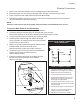
Initial Start-Up Filling the Booster ATTENTION VERIFY THE CORRECT VOLTAGE IS SUPPLIED TO THE MACHINE THE CORRECT SUPPLY VOLTAGE IS 115/208-240VAC/60/1. (Refer to the diagram on page 3.) Note: The dishwasher contains a built-in booster heater that was drained prior to shipment and must be filled with water before operating the dishwasher. Booster Fill Switch The booster heater is filled using the Booster Fill Switch.
Initial Start-Up Filling the Booster (continued) B) Press and hold the Booster Fill Switch down to the BOOSTER FILL position until you hear the water spraying inside the dishwasher wash tank, then release the switch. RINSE WASH RE TEMPERATU ON OFF BOOSTER FILL B C) Push the switch up to the ON position and release. The booster tank is filled.
Initial Start-up Check List 1. Remove any protective film from dishwasher. Check the interior for foreign material. 2. Make sure that the dishwasher is permanently located. 3. Make sure that all utility connections are complete. 4. Make sure that the flexible drain hose and the hot water fill hose are not kinked. 5. Make sure that the chemical supply containers are full and that the chemical pick-up tubes are installed in the proper containers. 6. Make sure that the sump filter is in place. 7.
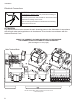
Initial Start-up Chemical Dispensing Pumps ATTENTION Contact a local chemical supplier for detergent and rinse-aid chemicals. The detergent should be a non-chlorinated liquid detergent. The chemical dispensing pumps are adjusted by the chemical supplier. 1. The dishwasher is equipped with a built-in detergent dispensing pump and rinse-aid dispensing pump. (See the photographs below.) 2. The pumps are located on the lower panel behind the lower-front access panel. 3.
Initial Start-up Chemical Dispensing Pumps (continued) Chemical Injection Points The illustrations below show the location of the detergent and the rinse-aid injection points. Detergent Injection Point Rinse-aid Injection Point Detergent enters the wash tank compartment through a fitting on the rear wall of the wash tank compartment. The rinse-aid enters the final rinse piping at the top-rear of the dishwasher near the vacuum breaker.
Initial Start-up Chemical Dispensing Pumps Priming the Chemical Dispensing Pumps The chemical dispensing pumps must be primed before the dishwasher is operated. A 2-position PRIME switch is located on the front control panel to do this. The Detergent dispensing pump is primed when the Prime switch is pushed UP to the DET position. The Rinse-aid dispensing pump is primed when the Prime switch is pushed DOWN to the R/A position (see below). DET R/A ON PRIME EXT.
Initial Start-up Chemical Dispensing Pumps Adjusting the Chemical Dispenser Pumps The amount of detergent and rinse-aid that are dispensed during the dishwasher cycle are controlled by adjustable cams on the timer assembly. Variables such as the type of chemicals used and the hardness of the water supply often require that the timer cam settings must be changed. It is recommended that the chemical supplier make these adjustments. (Refer to the illustration below).
Operation Normal Wash Mode Follow the instructions below to operate the dishwasher in a Normal Wash Mode. A Safe-T-Temp feature holds the dishwasher in a wash mode if the booster heater temperature is below 180ºF/82ºC. 1. Turn the main power on at the main circuit breaker. 2. Install the sump filter, overflow tube and spray arms. 3. Make sure the flexible drain hose and the flexible fill hose are not kinked, then turn the water supply on. 4. Close the dishwasher front door. 5.
Operation Normal Wash Mode (continued) 11. Opening the door when the dishwasher is in-cycle will stop the dishwasher. The cycle will resume automatically when the dishwasher door is closed fully. 12. The final rinse cycle begins at the end of the wash cycle and runs for approximately 15-seconds Check the RINSE temperature gauge during the final rinse and make sure that it indicates a minimum of 180ºF/82ºC. The acceptable range of operation is180-195ºF/82-91ºC. 13.
Cleaning and Maintenance Cleaning After Each Meal Period or every 8 Hours of Operation. 1. Press the lighted power switch to the OFF position. The power switch light will go out. 2. Open the door and remove the overflow tube from the wash tank sump. 3. Inspect and clean the overflow tube rubber seal 4. Close the door. 5. Push and hold the drain switch until all of the water has drained. 6. Remove the sump filter carefully to keep the soil or waste particles from falling into the sump. 7.
Cleaning and Maintenance Cleaning At the End of the Day 1. Perform Steps 1-8 on the previous page. 2. Remove the upper and lower rinse and wash spray arms. The spray arms are interchangeable. 3. Unscrew the rinse arm pin (A). Remove the rinse arm assemblies 4. Clean the final rinse arm nozzles using a small paper clip (B). 5. Remove the rinse arm end plugs (C) if necessary, and flush the rinse arm with clean water. 6. Re-install the rinse arm end plugs if they were removed. 7.
Cleaning and Maintenance De-liming Minerals accumulate on the interior surfaces of the dishwasher. The deposits have a white haze and, in cases of heavy accumulation, may appear as a granular solid. The generic name for mineral deposits is lime. The removal of lime deposits is called de-liming. Your dishwasher should be delimed regularly; how often will depend on the mineral content of your water. Inspect your machine interior for lime deposits.
Cleaning and Maintenance Maintenance Follow the maintenance schedules below to keep the dishwasher operating most efficiently. Daily Maintenance 1. Check all of the wash arm and rinse arm spray jets and clean as necessary. 2. Make sure that the water supply is on and that the drain is not clogged. 3. Check the temperature gauges and/or displays to ensure that they are operating. 4. Make sure that dish racks are in good condition. 5. Check the chemical containers and refill as required. 6.
Troubleshooting Troubleshooting Follow the troubleshooting guide below in the event that your dishwasher does not operate as expected. Perform the basic checks below before calling an authorized service agent: 1. Make sure that the main water supply is turned on. 2. Make sure that the main power is turned on. 3. Make sure that the flexible water fill and drain hoses are not kinked. Condition Cause Solution Dishwasher will not run. Door not closed. Main power OFF. Dishwasher OFF.
Blank Page This Page Intentionally Left Blank 20
Model UC65e - Electrical Schematic TO CUSTOMERS DISCONNECT SWITCH PER LOCAL ELECTRICAL CODE 115-208/230V/1PH 60HZ L1 L2 PS 1 BFS 1L1 N GND L1 1 TT TS 3 4 5 L2 1L2 WHTR POL 7 10 25 1 1 HC1 1H2 19 1 HC1 DOOR SWITCH 9 DRAIN SWITCH 6 8 CPS N 1H1 EWL EXT. WASH SWITCH 1HTR BOOSTER HEAT 208/230 VAC 4 kW 11 START SWITCH 13 26 SR1 23 SR1-2 WP WPR 12 SR 2 6 2 2 13 1 3 HOMING CAM 15 3 EXT.
22 CMA Dishmachines 8 SAFE-T-TEMP 7 EXTENDED WASH 6 RINSE AID PUMP 5 DET PUMP 4 RINSE VALVE 3 DRAIN PUMP 2 WASH PUMP 1 HOMING CAM TIME (SEC.) 0 6 10 20 30 40 UC65e 50 60 TIMING CHART 70 80 90 100 110 05CTIME DRAWING NO.
Theory of Operation - Fill/Drain Timer Fill/Drain Timer - Theory of Operation The Fill/Frain Timer provides both automatic fill and semi-automatic drain functions for the dishwasher. It is located on the back of the electrical component panel and it operates as follows: Fill 1. Main power, (115VAC), must be present at the Hotline and Neutral terminals of the fill/drain timer. 2. Turning the machine ON/OFF switch ON, sends 115VAC to the "SW Power" terminals which activates the initial fill. 3.
Blank Page This Page Intentionally left Blank 25