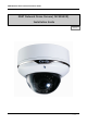
XNET Network Dome Camera Installation Guide XNET Network Dome Camera( IVC5055VR) Installation Guide Ver. 1.
XNET Network Dome Camera Installation Guide About this Manual A compatibility and durability test ensured this product’s high performance. This manual is for XNET IP Dome Camera users only, and it describes operations related to XNET IP Dome Camera. Please read this manual thoroughly paying attention to cautions and warnings before using the product even if you have used similar products before. Important Notices The copyright of this manual is owned by CNB Technology Inc.
XNET Network Dome Camera Installation Guide Index 1. About XNET .............................................................................................................. 4 1.1. About XNET ........................................................................................................ 4 1.2. Features of XNET ................................................................................................. 4 1.3. Applications .......................................................................
XNET Network Dome Camera Installation Guide 1. About XNET 1.1. About XNET XNET is an internet based security and surveillance system that is compatible with various network conditions through easy installation and user interface as well as multi-functional compressor Codec such as H.264, MJPEG. XNET provides stable real-time surveillance by real time video/ audio at 1080P level, local storage for any network problems, and hybrid IP technology that can be used with existing analog CCTV devices. 1.2.
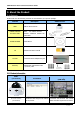
XNET Network Dome Camera Installation Guide 2. About the Product 2.1. Contents Please make sure the following contents are included when you open the package. Contents XNET POWER ADAPTOR AC Power Cable Description Additional info. XNET IP Dome Camera INPUT : 100~240VAC 50-60Hz OUTPUT : 12VDC 2A AC24V 2.5A 2Jack Cable GUIDE PATTERN CD Guide Pattern Software and User’s manual DC JACK Connect the Power Adaptor DC jack Accessory SCREW 3EA, Wall Anchors 3EA L (wrench) 1EA 2.2.
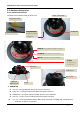
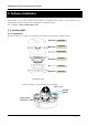
XNET Network Dome Camera Installation Guide 2.3. Hardware Designation 2.3.1. Switch and Controls This shows Camera module inside the dome cover. Analog video output Analog Video Output Factory Reset button Power Terminal Act,Link LED Recalls factory default configurations EVENT LED : EVENT Alarm Out signal is turned on.
XNET Network Dome Camera Installation Guide 2.3.2 Connecting Cables 1 2 3 4 5 6 7 8 9 LINE COLOR BROWN ORANGE BLUE GREEN RED WHITE BLACK GRAY YELLOW FUNCTION Alarm-Out(+) Alarm-Out(-) Alarm-In(+) Alarm-In(-) MIC/Line-in Line-Out GND Not Used Not Used Power Input(#1, #2) Use the cable adapter(DC12V JACK) in the package to connect power. Please use the accessory power supply provided in the package. Except when connected to AC24V DC jack please use(DC12V/2A,AC24V 2.
XNET Network Dome Camera Installation Guide Factory Reset Press and hold for more than 3 seconds while power is on to recall factory default settings Network Cable This Ethernet terminal connects to 100Mbps LAN through an RJ-45 cable. When optional PoE is used, the power will be supplied from the Network Cable. Network cable of this product is not water proof SD CARD SLOT : Enables recording of video data to an external memory device upon occurrence of an event.
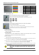
XNET Network Dome Camera Installation Guide 2.3.3 Connecting to Alarm Devices Alarm Input Wires from various sensor type (IR, heat, and magnetic) can be connected to Alarm in(+)/(-) terminal as shown in figure 2.5. (NC or NO of sensor input can be selected at Menu screen.) Alarm Sensor device requires a separate power source. Internal Circuitry External Circuitry Alarm Output This terminal can only be connected up to DC 30V/400mA.
XNET Network Dome Camera Installation Guide 3. Software Installation This section provides brief guidelines to install the XNET quickly and to monitor XNET’s Video and Audio signals easily. If you have questions about details not explained in this section or if the product is not functioning as described, please refer to FAQ before contacting the store. Our homepage is http://www.cnbtec.com. 3.1. Installing XNET 3.1.1. Installation Mount the Camera to a ceiling or a wall.
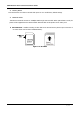
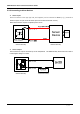
XNET Network Dome Camera Installation Guide 1.1.2. Cable Connection Connect XNET to PC directly User can monitor and configure XNET camera by connecting it to your PC directly. A. Connect XNET camera to your PC directly using a LAN cable like below. COMPUTER Crossover Network Cable NOTE: XNET camera’s IP address will be automatically set to the default value, 192.168.123.100, after connecting XNET camera to your PC directly. (This process approximately takes 20~30 seconds) B.
XNET Network Dome Camera Installation Guide C. Please insert the Setup CD into your CD-ROM drive, and then please setup IPInstaller program. D. Please click ‘Next’ button when the Setup screen appear. E. Please click ‘Install’ button to begin the Installation. F. Please click ‘Finish’ button to complete the installation.
XNET Network Dome Camera Installation Guide G. XNET IP Installer program is automatically launched like below right after the program installation. Please double click XNET camera on the list. H. XNET camera is successfully connected to your PC. (Internet Explorer will prompt you to install ActiveX. In order to view video, you must accept the ActiveX download. ) NOTE: Please select Setting menu for XNET camera configuration. If the login prompt appears, please enter User name and Password.
XNET Network Dome Camera Installation Guide Connect XNET with a router Please connect XNET camera and PC to a router using LAN cables like below. NETWORK HUB COMPUTER Direct Network Cable ` NOTE: If DHCP server is enabled at your router, XNET camera automatically receives an IP address from your router. Otherwise, XNET camera’s IP address will be automatically set to the default value, 192.168.123.100.
XNET Network Dome Camera Installation Guide 3.2. Installing IP-Installer Software and Configuring IP address 3.2.1. About IP-Installer A unique IP address has to be configured in order to connect IP camera and monitoring PC to a network. IPInstaller software provided in the Installation CD (included in the package and also available to download from our website http://www.cnbtec.com) will configure IP address easily. If your network have a DHCP server that automatically assigns IP addresses to IP cameras.
XNET Network Dome Camera Installation Guide B. Select the camera of which you wish to change the IP address and click (Set IP Address) button to bring up the following box in Figure 3-3. Figure 3-3. IP Address box C. When you enter the IP address and click Set button, the box shown in Figure 3-4 will appear. Figure 3-4. Select Network Adapter Box D. Select the adapter and click select button to change the IP address of the camera.
XNET Network Dome Camera Installation Guide 4. Using Web Viewer Connecting to network devices can be done using internet web browser or “XNET-CMS” software. This guide explains about using internet web browser only. For instructions on how to configure network connection using XNET-CMS software, please refer to XNET-CMS Manual, which can be found in the installation CD. 4.1. Logging In Enter the IP address of the device on the address bar of your web browser and press enter key.
XNET Network Dome Camera Installation Guide 4.2. Web Viewer Page Web viewer page consists of Video monitor screen and menu option buttons. Figure 4-2 Web Viewer Page Item Sub Item Capture - Description Captures and saves the current image as a still picture. The image is saved as jpeg file in the following folder: C:\xNetCapture Brings up Menu screen. Setting - Setup page for each XNET feature can be opened from this Menu screen. Please refer to [XNET Owner’s Manual] for detail.
XNET Network Dome Camera Installation Guide 5. Specification Specifications IVC5055VR Camera Signal System Progressive image processing Scanning System 16:9 Progressive Pixel Clock Image Sensor 80MHz 1/3" Progressive CMOS Sensor Sync. System Internal Effective Pixels Number 1920 (H) x 1080(V) 2.0 Mega Horizontal Resolution 1100 TV Lines Video Output Level Select NTSC/PAL 1.0Vp-p (BNC 75Ω, composite) Lens Built-in DC Iris Vari-focal Lens, f=3 ~ 10mm, F 1.3 Min. Illumination 0.
XNET Network Dome Camera Installation Guide 20 / 20