Wireless-G Broadband Router User’s Guide CWR-800
Table of Contents Chapter 1: Introduction The Wireless-G Broadband Router Features The Router’s Functions IP Addresses Router Setup Overview Chapter 2: Getting to Know the Wireless-G Broadband Router The Router’s Back Panel The Router’s Front Panel LEDs Chapter 3: Connect the Router Overview Wired Connection to a PC Wireless Connection to a PC Chapter 4: Configure the PCs Overview Configuring Windows 98 and Millennium PCs Configuring Windows 2000 PCs Configuring Windows XP PCs Chapter 5: Configure the Route
Chapter 1: Introduction CNet Smart Wireless-G Router is the upcoming 54Mbps wireless networking standard that’s almost five times faster than the widely deployed Wireless-B (802.11b) products found in homes, businesses, and public wireless hotspots around the country —but since they share the same 2.4GHz radio band, Wireless-G devices can also interoperate with existing 11Mbps Wireless-B equipment. Since both standards are built in, you can protect your investment in existing 802.
What’s an IP Address? IP stands for Internet Protocol. Every device on an IP-based network, including PCs, print servers, and routers, requires an IP address to identify its “location,” or address, on the network. This applies to both the Internet and LAN connections. There are two ways of assigning an IP address to your network devices. You can assign static IP addresses or use the Router to assign IP addresses dynamically.
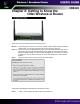
This User Guide covers the steps for setting up a network with the Router (see Figure 1-1). After going through “Chapter 2: Getting to Know the CNet Smart Wireless-G Router,” most users will only need to use the following chapters: • Chapter 3: Connect the Router This chapter instructs you on how to connect a cable or DSL modem to the Router and connect your PC(s) to the Router.
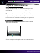
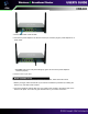
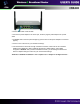
Chapter 2: Getting to Know the CNet Wireless-G Router The Router’s ports are located on the Router’s back panel. The Internet port is where you connect your cable or DSL modem through an Ethernet network cable. Your modem connection will not work from any other port. Ports 1-4 These four LAN (Local Area Network) ports connect to network devices, such as PCs, print servers, and network attached storage (NAS).
WLAN Green. When Wireless network is active. The LAN Indicators LAN Green. The LAN LED serves two purposes. If the LED is continuously lit, the Router is successfully connected to a device through the corresponding port. If the LED is flickering, the Router is actively sending or receiving data over that port. The Internet Indicators WAN Green. The WAN LED lights up when a successful connection is made between the Router and your cable or DSL modem (the Internet).
Chapter 3: Connect the Router The Router’s setup consists of more than simply plugging hardware together. You will have to configure your networked PCs to accept the IP addresses that the Router assigns them (if applicable), and you will also have to configure the Router with setting(s) provided by your Internet Service Provider (ISP). The installation technician from your ISP should have left the setup information for your modem with you after installing your broadband connection.
4. Power on the cable or DSL modem. 5. Connect the power adapter to the Router’s Power port, and then plug the power adapter into a power outlet. • The Power LED on the front panel will light up green as soon as the power adapter is connected properly. 6. Power on one of your PCs. If you want to use a wireless connection to access the Router, follow these instructions: 1. Before you begin, make sure that all of your network’s hardware is powered off, including the Router, PCs, and cable or DSL modem. 2.
3. Power on the cable or DSL modem. 4. Connect the power adapter to the Power port, and then plug the power adapter into a power outlet. • The Power LED on the front panel will light up green as soon as the power adapter is connected properly. 4. Power on one of the PCs on your wireless network(s). 5. For initial access to the Router through a wireless connection, make sure the PC’s wireless adapter has its SSID set to CNET_Wireless (the Router’s default setting), and its WEP encryption is disabled.
Chapter 4: Configure the PCs The instructions in this chapter will help you configure each of your computers to be able to communicate with the Router. To do this, you need to configure your PC’s network settings to obtain an IP (or TCP/IP) address automatically, so your PC can function as a DHCP client. Computers use IP addresses to communicate with the Router and each other across a network, such as the Internet First, find out which Windows operating system your computer is running.
3. Click the IP Address tab. Select Obtain an IP address automatically. 4. Now click the Gateway tab, and verify that the Installed Gateway field is blank. Click the OK button. 5. Click the OK button again. Windows may ask you for the original Windows installation disk or additional files. Check for the files at c:\windows\options\cabs, or insert your Windows CD-ROM into your CDROM drive and check the correct file location, e.g., D:\win98, D:\win9x, etc. (if “D” is the letter of your CD-ROM drive). 6.
3. Make sure the box next to Internet Protocol (TCP/IP) is checked. Highlight Internet Protocol (TCP/IP), and click the Properties button. 4. Select Obtain an IP address automatically. Once the new window appears, click the OK button. Click the OK button again to complete the PC configuration. 5. Restart your computer. Go to “Chapter 5: Configure the Router’s Basic Settings.” The following instructions assume you are running Windows XP with the default interface.
3. Make sure the box next to Internet Protocol (TCP/IP) is checked. Highlight Internet Protocol (TCP/IP), and click the Properties button. 4. Select Obtain an IP address automatically. Once the new window appears, click the OK button. Click the OK button again to complete the PC configuration. Go to “Chapter 5: Configure the Router’s Basic Settings.” .
Chapter 5: Configure the Router’s Basic Settings This chapter will show you how to configure the Router to function in your network and gain access to the Internet through your Internet Service Provider (ISP). Detailed description of the Router’s web-based utility can be found in “Chapter 6: The Router’s Web-based Utility.” The instructions from your ISP tell you how to set up your PC for Internet access.
3. The web-based utility will appear with the Basic Settings tab selected. Select the time zone for your location. 4. Based on the setup instructions from your ISP, you may need to provide the Host Name and Domain Name (usually cable ISPs require them). These fields allow you to provide a host name and domain name for the Router and are usually left blank. The values for the Router’s LAN IP Address and Subnet Mask are shown on the Basic Settings screen. The default values are 192.168.1.
DHCP Auto Config If you are connecting through DHCP or a dynamic IP address from your ISP, perform these steps: A. Keep the default setting, DHCP Auto Config, as the Configuration Type. B. Click the Apply button to save the setting, or click the Cancel button to clear the setting and start over. When you are finished, proceed to step 6. Static IP Address If you are connecting through a static or fixed IP address from your ISP, perform these steps: A. Select Static IP as the Configuration Type. B.
F. Click the Apply button to save the settings, or click the Cancel button to clear the settings and start over. When you are finished, proceed to step 6. PPPoE If your DSL provider says that you are connecting through PPPoE (you use a user name and password to access the Internet), perform these steps: A. Select PPPoE as the Configuration Type. B. Enter the User Name. C. Enter the Password.
D. Click the Apply button to save the settings, or click the Cancel button to clear the settings and start over. When you are finished, proceed to step 6. PPTP If you are using a PPTP connection, check with your ISP for the necessary setup information. After you have entered your setup information, click the Apply button to save the settings, or click the Cancel button to clear the settings and start over. When you are finished, proceed to step 6. 6.
D. Select security mode, click the Apply button to save your settings. For more information, refer to “Chapter 6: The Router’s Web-based Utility.” 7. If you haven’t already done so, click the Apply button to save your Setup settings. Close the web browser. 8. Restart your computers so that they can obtain the Router’s new settings. Test the setup by opening your web browser from any computer and entering http://www.cnet.com.tw.
Chapter 6: The Router’s Web-based Utility Use the Router’s web-based utility to administer it. This chapter will describe each web page in the Utility and each page’s key functions. The utility can be accessed via your web browser through use of a computer connected to the Router. The “Basic settings” , “Security” ,”System”,” Status”, and “Help” screens are available for basic setup.
Firmware Version This shows the version and date of the firmware you are using. Future versions of the Router’s firmware will be posted and available for download on the CNet website at http://www.cnet.com.tw. Time Zone Select the time zone for your location. Internet MAC Address The MAC Address of the Internet interface is displayed here. Host Name and Domain Name These fields allow you to supply a host and domain name for the Router. Some ISPs, usually cable ISPs, require these names as identification.
1. Select Enable. 2. Enter your adapter’s MAC address in the MAC Address field. 3. To save your new settings, click the Apply button. To cancel your changes, click the Cancel button. To get more information about the features, click the Help button. To disable MAC address cloning, keep the default setting, Disable. DHCP Auto Config By default, the Router’s Configuration Type is set to DHCP Auto Config, and it should be kept only if your ISP supports DHCP or you are connecting through a dynamic IP address.
Static IP Address If you are required to use a permanent IP address to connect to the Internet, then select Static IP. IP Address This is the Router’s IP address, when seen from the WAN, or the Internet. Your ISP will provide you with the IP Address you need to specify here. Subnet Mask This is the Router’s Subnet Mask, as seen by external users on the Internet (including your ISP). Your ISP will provide you with the Subnet Mask.
PPPoE Some DSL-based ISPs use PPPoE (Point-to-Point Protocol over Ethernet) to establish Internet connections. If you are connected to the Internet through a DSL line, check with your ISP to see if they use PPPoE. If they do, you will have to enable PPPoE. User Name and Password Enter the User Name and Password provided by your ISP. Connect on Demand: Max Idle Time You can configure the Router to cut the Internet connection after it has been inactive for a specified period of time (Max Idle Time).
PPTP Point to Point Tunneling Protocol (PPTP) is a service Internet IP Address This is the Router’s IP address, when seen from the Internet. Your ISP will provide you with the IP Address you need to specify here. Subnet Mask This is the Router’s Subnet Mask, as seen by external users on the Internet (including your ISP). Your ISP will provide you with the Subnet Mask. Default Gateway Your ISP will provide you with the Default Gateway Address.
Wireless MAC Address The MAC Address of the wireless interface is displayed here. Channel Select the appropriate channel from the list provided to correspond with your network settings, between 1 and 11 (in North America). All devices in your wireless network must use the same channel in order to function correctly. SSID Broadcast When wireless clients survey the local area for wireless networks to associate with, they will detect the SSID broadcast by the Router.
Wireless Security CNet Smart Wireless-G Router provides encryption types: (A) WEP (B) WPA (A) WEP (Wired Equivalent Privacy) Transmit Key Select which WEP key (1-4) will be used when the Router sends data. Make sure the receiving device is using the same key. WEP Encryption Select the level of WEP encryption you wish to use, 64-bit 10 hex digits or 128-bit 26 hex digits.
(B) WPA ( Wi-Fi Protected Access ) Setting WEP Pre-Shared Key 1. From the “Security Mode” drop-down menu, select “WPA Pre-Shared Key” 2. For “WPA Algorithms”, Select “TKIP” (Temporal Key Integrity Protocol) or “AES” (Advanced Encryption Standard). This setting will have to be identical on the clients that you set up. 3. Enter your pre-shared key. This can be letters, numbers, or symbols. This same key must be used on all of the clients that you set up. 4. Click “Apply” to finish.
The Security screen allows you to change the Router’s security settings. You should change the factory default password, which is admin, to your own as soon as possible. All users who try to access the Router’s web-based utility or Setup Wizard will be prompted for the Router’s password. Router Password The new Password must not exceed 32 characters in length and must not include any spaces. Enter the new Password in the second field to confirm it.
(PPTP) used by to enable the operation of a virtual private network (VPN) over the Internet. PPTP - Point-to-Point Tunneling Protocol is the method used to enable VPN sessions to a Windows NT 4.0 or 2000 server. To allow PPTP tunnels to pass through the Router, PPTP Pass-Through is enabled by default. To disable PPTP Pass-Through, uncheck the box next to PPTP. Web Filters Using the Web Filters feature, you may enable up to four specific filtering methods.
(DHCP) server function. The Router can be used as a DHCP server for your network. A DHCP server automatically assigns an IP address to each computer on your network. If you choose to enable the Router’s DHCP server option, you must configure all of your network PCs to connect to a DHCP server (the Router), and make sure there is no other DHCP server on your network. DHCP Server DHCP is enabled by factory default.
Restore Factory Defaults Click the Yes button to reset all configuration settings to their default values, and then click the Apply button. Any settings you have saved will be lost when the default settings are restored. This feature is disabled by default. Firmware Upgrade New firmware versions are posted at www.cnet.com.tw and can be downloaded for free. If the Router already works well, there’s no need to download a newer firmware version, unless that version has a new feature that you want to use.
UPnP This Router support UPnP ( Universal Plug and Play). A Router Internet Connection icon should be visible on the Notification Area of any MS Windows XP machine on the LAN side.If you want to watch what application to use in this computer, select Enable to enable it. Fro example You use MSN Message in your computer: 1. Double click ” My Network Places” 2. Click “ View network connections”. You will see the following page. The Internet Gateway is CNet Smart Wireless-G Router. 3.
4. Click “Properties”. You will see the following page. 5.
Multicast Pass-Through IP Multicasting occurs when a single data transmission is sent to multiple recipients at the same time. Using the Multicast Pass- Through feature, the Router allows IP multicast packets to be forwarded to the appropriate computers. Keep the default setting, Enable, to support the feature, or select Disable to disable it. Remote Management This feature allows you to manage your Router from a remote location, via the Internet. To disable this feature, keep the default setting, Disable.
The Outgoing Access Log gives you a log of all outgoing Internet traffic. For each activity, it displays the LAN IP address, the Destination URL or IP address of the Internet site accessed, as well as the Service/Port Number used. Click the Refresh button to update the logs. Click the Close button to return to the System screen. To save your changes on this page, click the Apply button. To cancel any unsaved changes on this page, click the Cancel button.
The Status screen displays the Router’s current status and configuration. All information is read-only. It will updates and display automatically every 10 seconds. Firmware Version The version number of the firmware currently installed is displayed here. Current Time The current date and time are displayed here. Host Name The Host Name is the name of the Router. This entry is necessary for some ISPs. Domain Name The Domain Name is the name of the Router's domain. This entry is necessary for some ISPs.
The Help screen offers links to all of the Router’s technical support resources and the application that upgrades the Router’s firmware. For additional information about each screen of the web-based utility, click the appropriate link on the left-hand side of the Help screen.
The following instructions are for advanced users or users whose setup needs require special configuration. When you click the Advanced Settings tab, you will be able to set up these features. There are six additional tabs available. Advanced Wireless - Allows you to customize data transmission and 802.1x settings for your wireless network(s). Access Control - Enables you to set up filters that block specific internal users from Internet access.
feature, keep the default setting, Disable. To set up a filter, click Enable, and follow these instructions: 1. If you want to block specific wireless-equipped PCs from communicating with the Router, then keep the default setting, Prevent PCs listed from accessing the wireless network. If you want to allow specific wireless equipped PCs to communicate with the Router, then click the radio button next to Permit only PCs listed to access the wireless network. 2. Click the Edit MAC Filter List button.
Authentication Type The default is set to Auto, which allows either Open System or Shared Key authentication to be used. For Open System authentication, the sender and the recipient do NOT use a WEP key for authentication. For Shared Key authentication, the sender and recipient use a WEP key for authentication. If you want to use only Shared Key authentication, then select Shared Key. Transmission Rate The default setting is Auto. The range is from 1 to 54Mbps.
256-2346 bytes. It specifies the maximum size for a packet before data is fragmented into multiple packets. If you experience a high packet error rate, you may slightly increase the Fragmentation Threshold. Setting the Fragmentation Threshold too low may result in poor network performance. Only minor modifications of this value are recommended. Operation Mode CNet Smart Wireless-G Router support three operation mode: Access Point/Bridge/Repeater.
Enter Policy Name Policies are created from the fields presented here. To create a policy: 1. Enter a Policy Name in the field provided. 2. Click the Edit List of PCs button. This will open the List of PCs screen. From this screen, you can enter the IP address or MAC address of any PC to which this policy will apply. You can even enter ranges of PCs by IP address. Click the Apply button to save your settings, the Cancel button to undo any changes, and the Close button to return to the Filters tab. 3.
5. By selecting the appropriate setting next to Days and Time, choose when Internet access will be filtered. 6. Lastly, click the Apply button to save and activate this policy. Internet Access can also be filtered by URL Address, the address entered to access Internet sites, by entering the address in one of the Website Blocking by URL Address fields. If you do not know the URL Address, filtering can be done by Keyword by entering a keyword in one of the Website Blocking by Keyword fields.
Customized Applications In the field provided, enter the name you wish to give each application. External Port For each application, enter the number of the External Ports (the port numbers seen by users on the Internet) in the appropriate fields. (To find out the port range, check your application’s documentation.) If there is only one External Port, enter its number in both External Port fields.
2. Enter the Outgoing Port Range used by the application. Check with the Internet application for the port number(s) needed. 3. Enter the Incoming Port Range used by the application. Check with the Internet application for the port number(s) needed. 4. Click the Apply button to save your changes. Click the Cancel button to cancel your unsaved changes. Click the Close button to return to the Port Forwarding screen. To save your changes on this page, click the Apply button.
To set up routing: 1. Choose the correct working mode. Select Gateway if the Router is hosting your network’s connection to the Internet (recommended for most users). Select Router if the Router exists on a network with other routers. 2. If you selected the Gateway mode, click the Apply button. If you selected the Router mode, proceed to step 3. 3. For Dynamic Routing, the default is Disable.
Dynamic DNS The Router offers a Dynamic Domain Name System (DDNS) feature. DDNS lets you assign a fixed host and domain name to a dynamic Internet IP address. It is useful when you are hosting your own website, FTP server, or other server behind the Router. Before you can use this feature, you need to sign up for DDNS service at www.dyndns.org, or www.TZO.com, DDNS service providers. DDNS Service To enable DDNS Service, select Enable and follow these instructions: 1.
Status The status of the DDNS service connection is displayed here. To save your changes on this page, click the Apply button. To cancel any unsaved changes on this page, click the Cancel button. To get more information about the features, click the Help button. The SNMP tab, allows you to customize the Simple Network Management Protocol (SNMP) settings. SNMP is a popular network monitoring and management protocol.
Appendix A: Specifications Product Name Model Name Standards Channels Ports Cabling Type Data Rate LED Indicators Modulation Network Protocols Operating Humidity Operating Temp. Power Storage Humidity Storage Temp. Transmit Power Dimensions Certifications Smart Wireless-G Router CWR 800 IEEE 802.3, IEEE 802.3u, IEEE 802.11b, IEEE 802.11g 10-13 (France, Jordan) 1-11 (U.S.