Multi-Function Wireless A/P Router User’s Guide Model CNWR-811P Wireless Access Point Router W / Printer Sharing
TABLE OF CONTENTS CHAPTER 1 INTRODUCTION ..............................................................................................1 CNWR-811P Features .......................................................................................................1 Package Contents...............................................................................................................3 Physical Details .........................................................................................................
APPENDIX A TROUBLESHOOTING.................................................................................59 Overview...........................................................................................................................59 General Problems.............................................................................................................59 Internet Access .................................................................................................................
1 Chapter 1 Introduction This Chapter provides an overview of the CNWR-811P's features and capabilities. Congratulations on the purchase of your new CNWR-811P Multi-Function Wireless A/P Router. The CNWR-811P is a multi-function device providing the following services: • Shared Internet access via an ADSL or Cable modem. • Wireless LAN Access Point (base station) for equipment compliant with the IEEE802.11b (DSSS) specifications.
CNWR-811P User Guide Internet Access Features • Shared Internet Access. All users on the LAN can access the Internet through the CNWR-811P, using only a single external IP Address. The local (invalid) IP Addresses are hidden from external sources. This process is called NAT (Network Address Translation). • ADSL & Cable Modem Support. The CNWR-811P has a 10BaseT Ethernet port for • PPPoE Support. Connect to your ISP using PPPoE (PPP over Ethernet), if your ISP • Fixed or Dynamic IP Address.
Introduction Security Features • Configuration Data. Optional password protection is provided to prevent unauthorized • Access Control Features. The LAN Administrator can limit Internet access by individ- • Wireless LAN Security. WEP (Wired Equivalent Privacy) is supported, as well as • Firewall Protection. All incoming data packets are monitored and all incoming server users from modifying the configuration. ual workstations. Wireless access control via station address.
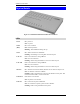
CNWR-811P User Guide Physical Details Figure 2: CNWR-811P Multi-Function Wireless A/P Router LEDs Power On - power on Off - no power Status (Red) On - Error condition. Off - Normal operation Blinking - This LED blinks during start up. WAN On - WAN connection is established. Flashing - transmitting or receiving data via the WAN port. LAN: 10 On - LAN connection is using 10BaseT. Off - No LAN connection.
Introduction Rear Panel Figure 3: Rear Panel Printer Port Standard parallel printer port. If you wish to share a printer, connect it here. WAN port (10BaseT) Connect the ADSL or Cable Modem here. If your modem came with a cable, use the supplied cable. Otherwise, use a standard LAN cable. DIP switches Refer to the following table.. PC port (10/100BaseTX) If connecting directly to your PC (no Hub) use this port and a standard LAN cable (RJ45 connectors).
CNWR-811P User Guide DIP Switches DIP Switch Setting Description 1=off 2=off Normal Operation 1=off 2=on DHCP Server function disabled. 1=on 2=off Used to restore Default IP Address and clear Password (See below) 1=on 2=on Normal Operation. Restore Default IP Address and Clear Password If the CNWR-811P's IP Address or password is lost, the following procedure can be used to recover from this situation. 1. Turn the power to the CNWR-811P OFF. 2. Set DIP switch 1 ON. 3.
2 Chapter 2 Installation This Chapter covers the physical installation of the CNWR-811P. Requirements • Ethernet LAN (10/100BaseTX) and the TCP/IP protocol. • For Internet Access, an ADSL or Cable modem, and an Internet Access account with an ISP. • To use the Wireless Access Point, all Wireless devices must be compliant with the IEEE802.11b specifications. ¼ The CNWR-811P's PCMCIA slot is designed to use ONLY 3.3V PCMCIA Wireless cards. Procedure Figure 4: Installation Diagram 1.
CNWR-811P User Guide 3. Connect LAN Cable Connect a standard LAN cable from a 10BaseT or 100BaseTX Hub on your LAN to the “HUB” port on the CNWR-811P. 4. Connect WAN Cable Connect the ADSL or Cable modem to the WAN port on the CNWR-811P. Use the cable supplied with your modem. If no cable was supplied, use a standard LAN cable. 5. Connect Printer Cable Use a standard parallel printer cable to connect your printer to the Printer port on the CNWR-811P. 6.
3 Chapter 3 Configuration This Chapter provides details of the configuration process. Overview This chapter describes the procedure for: • LAN setup • WAN port configuration for Internet Access • Wireless access point configuration PCs on your local LAN may also require configuration. For details, see Chapter 4 - PC Configuration. Other configuration may also be required, depending on which features and functions of the CNWR-811P you wish to use.
CNWR-811P User Guide Configuration Program The CNWR-811P contains a HTTP server. This enables you to connect to it, and configure it, using your Web Browser. Most Browsers should work, provided they support HTML tables and forms. Preparation Before attempting to configure the CNWR-811P, please ensure that: • Your PC can establish a physical connection to the CNWR-811P. The PC and the CNWR811P must be directly connected (using the “PC” port on the CNWR-811P) or on the same LAN segment.
Configuration Password If you have assigned a password to the CNWR-811P you will be prompted for the password, as shown below. Figure 5: Password Dialog • Leave the "User Name" blank. • Enter the password for this device, if one has been set. If no password has been set, this dialog will not appear. Navigation & Data Input • Use the menu bar on the left of the screen, and the "Back" button on your Browser, for navigation.
CNWR-811P User Guide LAN Screen The LAN screen, like the example below, will be displayed when you first connect. Figure 6: LAN Screen LAN Configuration. For most users, the default values for these fields should be satisfactory, and no changes will be required. If your LAN contains an existing Router or Routers, refer to Chapter 6 - Routing. Data – LAN Screen TCP/IP IP Address IP address for the CNWR-811P. Use the default value of 192.168.0.
Configuration DISABLED, and the existing DHCP server must be re-configured. See Chapter 5 for further details. Start IP Address Finish IP Address The IP Start Address and IP Finish Address fields set the values used by the DHCP server. This range also determines the number of DHCP clients supported. (Maximum 253.) DNS (Domain Name Server) DNS (Domain Name Server) IP Addresses If your ISP uses a “Dynamic IP Address”, then the DNS is also provided dynamically.
CNWR-811P User Guide WAN Configuration To configure the WAN port: • Select WAN from the menu. • Select the appropriate connection type (Direct Connection or PPPoE) on the screen below, then Click the “Configure” button. Figure 7: WAN Screen Tip: If your connection documentation does not refer to PPPoE, select Direct Connection.
Configuration Hardware (MAC) Address Also called Network Adapter Address or Physical Address. Provide this value to your ISP if requested. If you did not provide this value when first connected, there is no need to provide it now. IP Address Dynamic IP Address (DHCP Client) Leave this enabled if you want your ISP to allocate an IP Address to the CNWR-811P upon connection. Fixed IP Address Select this if using a fixed IP Address. If this option is selected, the following data must be entered.
CNWR-811P User Guide WAN - PPPoE Figure 9: WAN Port - PPPoE Data – WAN (PPPoE) Account Account/User Name The name of the Internet account provided by your ISP. Password & Verify Enter the password for the above account. Re-enter the password in the Verify field, to ensure it is correct. IP Address IP Address provided by ISP Normally, this is Dynamic; use this setting if your ISP did not provide an IP Address. If your ISP did provide an IP Address, select Fixed and enter the value they provided.
Configuration Wireless Configuration The CNWR-811P settings must match the other Wireless stations. An example Wireless screen is shown below. Figure 10: Wireless Screen Data – Wireless Screen Configuration Regulatory Domain It is illegal to use this device in any location outside of the regulatory domain. Station name This is the same as the Device (Host) Name on the WAN screen. On your PC, some Wireless status screens may display this name as the Access Point in use.
CNWR-811P User Guide Channel No. Select the value you wish to use on your Wireless LAN. If you experience lost connections and/or slow data transfers you may need to experiment with different channels to see which is the best. WEP Data Privacy Off If OFF (default), data is NOT encrypted before being transmitted. 64 Bit Encryption • If selected, data is encrypted, using the default key, before being transmitted.
Configuration New station Address • Use this field to add a new station to the list. Just enter its address here, and click the "Add" button. • Use the software supplied with your Wireless unit to determine its address. The address consists of 12 letters (A..F) and digits (0..9) like this example: 10F810A81091 The address may be shown with separators ( : or - ) between each pair of characters. Do NOT enter the separators ( : or - ) in this field.
CNWR-811P User Guide WAN Status Clicking WAN Status on the menu bar will take you to the WAN Status screen. The screen shown will depend on whether you are using a Direct Connection or PPPoE. WAN Status – Direct Connection Figure 11: WAN Status – Direct Connection Data WAN Status Physical Address The "Hardware" address of this device, as seen by other devices on the WAN. IP Address The IP Address of this device, as seen by devices on the WAN.
Configuration WAN Status – PPPoE Figure 12: WAN Status – PPPoE Status Data WAN Status Physical Address The "Hardware" address of this device, as seen by other devices on the WAN. IP Address The IP Address of this device, as seen by devices on the WAN. (This device has 2 IP Addresses; one for the local LAN, and another for the WAN port.) Network Mask The Network Mask (Subnet Mask) for the IP Address above. PPPoE Link Status This indicates whether or not the connection is currently established.
CNWR-811P User Guide Refresh Contact this device and update the Log data. Connection Log Messages Message Description Connect on Demand Connection attempt has been triggered by the "Connect on Demand" setting. Manual connection Connection attempt started by the "Connect" button. Reset physical connection Preparing line for connection attempt. Connecting to remote server Attempting to connect to the the ISP's server. Remote Server located ISP's Server has responded to connection attempt.
Configuration LAN/Device Status The LAN Status link on the menu will result in a screen like the example below. Figure 13: Status Screen Data – LAN/Device Status Device Firmware Version Version of the firmware (embedded software, including this program) which is currently installed. Hardware ID The hardware ID of this device, used by the manufacturer.
CNWR-811P User Guide Status Possible Status values are "Leased" (the IP Address is allocated to the device shown) or "Reserved" (the IP Address is not available). Note: The DHCP table will be empty unless the DHCP Server function is being used. If not empty, this table lists the devices on the LAN which have been allocated IP Addresses by the DHCP server function.
Chapter 4 PC Configura Configuration 4 This Chapter details the PC Configuration required on the local ("Internal") LAN. Overview For each PC, the following may to be configured: • TCP/IP network settings • Internet Access configuration • Network printer • Wireless configuration TCP/IP Settings If using the default CNWR-811P settings, and the default Windows 95/98 TCP/IP settings, no changes need to be made.
CNWR-811P User Guide Figure 15: IP Address (Win 95) Ensure your TCP/IP settings are correct, as follows: Using DHCP To use DHCP, select the radio button Obtain an IP Address automatically. This is the default Windows settings. Restart your PC to ensure it obtains an IP Address from the CNWR-811P. Using “Specify an IP Address” • If your PC is already configured, do NOT change the settings on the IP Address tab shown in Figure 15 above.
PC Configuration Figure 17: DNS Tab (Win 95/98) If your LAN has a Router, the LAN Administrator must re-configure the Router itself. Refer to Chapter 6 - Routing for details.
CNWR-811P User Guide Internet Access Configuration If you are using the CNWR-811P for Internet access: • Ensure that the DSL modem, Cable modem, or other permanent connection is functional. • Use the following procedure to configure your Browser to access the Internet via the LAN, rather than by a Dial-up connection. 1. 2. 3. Select Start Menu - Settings - Control Panel - Internet Options. Select the Connection tab, and click the Setup button.
PC Configuration Printing Setup The CNWR-811P provides printing support for 2 methods of printing from Windows: • Print Port Driver. After installing the Print Port Driver, Windows users can print directly to the CNWR-811P. Print jobs are spooled (queued) on each PC. The supplied Print Port Driver supports Windows 95/98, Windows ME, Windows NT4.0, and Windows 2000. • LPD/LPR Printing. If using Windows NT 4.0 Server or Windows 2000 Server, LPD/LPR printing can be used.
CNWR-811P User Guide If you see the following error message, either install Internet Explorer 4 or later, or follow the procedure in the "Trouble Shooting - Printing" section of Appendix A. 7. 8. A pop-up message will inform you if the port has been created successfully, and then the Windows Add Printer wizard will start. • Select the correct Printer Manufacturer and Model, or use the "Have Disk" option if appropriate. • If desired, change the Printer name so it indicates the device used (e.g.
PC Configuration Figure 19: Print Port Configuration Items shown on this screen are as follows: Port If desired, click Browse to select a different device. (The Select Device Port button is provided to allow this software to work with multi-port models.) The Port Name is shown in the Printer's Properties. Banner Retry Interval Check this option to print a banner page before each print job. • If using a PostScript Printer, check the PostScript box. • The User Name will be printed on the banner page.
CNWR-811P User Guide LPD/LPR Printing LPD/LPR printing can be used with Windows NT 4.0 Server or Windows 2000. No software needs to be installed. Windows NT 4.0 Server Configuration To use LPD printing, Microsoft TCP/IP Printing must be installed and enabled. This can be checked using Start-Settings-Control Panel-Network - Services. To install LPD printing using the CNWR-811P, follow this procedure: 1. 2. 3. 4. 5. 6. 7. 8. 9. Go to Start-Settings-Printer and invoke the Add Printer wizard.
PC Configuration Windows 2000 Server Configuration The LPD/LPR Port is not enabled by default. To enable it, use this procedure: 1. In Control Panel, select Add/Remove Programs, then Windows Components. 2. Select Other Network File and Print Services, then click the Details button. Figure 20: Adding LPD/LPR Port (Win 2000) 3. 4. Enable Print Services for Unix, and click OK. Click Next and complete the Wizard. Adding the Printer 1. Open your Printers folder, and start the Add Printer Wizard. 2.
CNWR-811P User Guide Figure 21: Windows 2000: Select Port 4. 5. 6. 7. 8. In the Dialog requesting Name of Address of server providing lpd, enter the IP address of the CNWR-811P. For Name of printer or print queue on that server, enter L1. Click OK, and then Next, and continue the Wizard. At the Select Sharing screen, select the Radio Button for Share As, and enter the shared printer name. The shared name is how other users will see this printer.
PC Configuration Macintosh Configuration The CNWR-811P currently does not support printing from the Macintosh, but you can access the Internet via the CNWR-811P. The procedure is as follows. 1. 2. 3. 4. Open the TCP/IP Control Panel. Select Ethernet from the Connect via pop-up menu. Select Using DHCP Server from the Configure pop-up menu. The DHCP Client ID field can be left blank. Close the TCP/IP panel, saving your settings.
5 Chapter 5 DHCP This Chapter covers the use of DHCP, using either an existing DHCP Server or the CNWR-811P's DHCP Server function. Overview If your LAN does not use DHCP, and you do not wish to use DHCP, you can ignore this chapter. What DHCP Does A DHCP (Dynamic Host Configuration Protocol) server allocates a valid IP address to a DHCP client (PC or device) upon request. • The client request is made when the client device boots.
DHCP Using another DHCP Server You can only use one (1) DHCP Server. If you wish to use another DHCP Server, rather than the CNWR-811P’s, the following procedure is required. 1. Disable the DHCP Server feature in the CNWR-811P. This setting is on the LAN screen. 2. Configure the DHCP Server to provide the CNWR-811P’s IP Address as the Default Gateway. To Configure your PCs to use DHCP This is the default setting for TCP/IP under Windows 95/98/ME.
6 Chapter 6 Routing This Chapter explains the Routing features of the CNWR-811P. Overview While the CNWR-811P includes a standard (static) routing table, this feature can be completely ignored if you do not have a router in your LAN. If you DO have a router, it is necessary to configure BOTH the Router and the Routing table in the CNWR-811P correctly, as described in the following sections. See Routing Example on page 40 for an example of configuring both the CNWR811P and the Router.
Routing Routing Table Data An entry in the routing table is required for each LAN segment on your Network, other than the segment to which this device is attached. The data in the Routing Table is as follows. Destination IP Address The network address of the remote LAN segment. For standard class "C" LANs, the network address is the first 3 fields of this Destination IP Address. The 4th (last) field can be left at 0. Network Mask The Network Mask used on the remote LAN segment.
CNWR-811P User Guide Routing Example Router A (192.168.1.80) Segment 1 (192.168.0.100) Segment 0 (192.168.1.xx) (192.168.0.xx) Wireless Router Router B (192.168.1.90) (192.168.2.70) (192.168.0.1) Segment 2 (192.168.2.xx) Figure 23: Routing Example For the LAN shown above, with 2 routers and 3 LAN segments, the required entries would be as follows. For the CNWR-811P's Routing Table The CNWR-811P requires 2 entries as follows. Entry 1 (Segment 1) Destination IP Address 192.168.1.
Routing For Router A's Default Route Destination IP Address 0.0.0.0 Network Mask 0.0.0.0 Gateway IP Address 192.168.0.1 (CNWR-811P's IP Address) For Router B's Default Route Destination IP Address 0.0.0.0 Network Mask 0.0.0.0 Gateway IP Address 192.168.1.
7 Chapter 7 Options This Chapter details the options available on the CNWR-811P's "Options" screen. Overview An example Options screen is shown below. Figure 24: Options Screen Password Once a password is entered, it is required in order to change the device configuration. Passwords are case sensitive and can be up to 8 alphanumeric characters (no spaces or punctuation). To create or change the password, enter the required password in both the New Password and Verify Password input fields.
Options NAT (Network Address Translation) NAT allows PCs on your LAN to share a single external (Internet) IP Address. This IP Address is supplied by your ISP. Use the following to determine whether or nor you need NAT. • For Internet access, NAT must be left On unless all PCs on your LAN have valid external IP Addresses. • In other situations, NAT is not normally required. With NAT disabled, the CNWR-811P will act as a static router.
Chapter 8 Advanced Inter Internet 8 This Chapter explains how to use the CNWR-811P's "Advanced Internet" features. Overview For situations where the CNWR-811P is being used to provide shared Internet access, the following advanced features are provided. • Special Internet Applications • Virtual Servers • DMZ This chapter contains details of the configuration and use of each of these features.
Advanced Internet Special Internet Applications This feature is only required if you wish to use Internet applications which require 2-way communication, multiple connections, or combined TCP/UDP connections. Examples of such applications are Internet Videoconferencing, Telephony, Games Servers, and other special-purpose Servers. Generally, you will become aware of the need for this feature when an Internet application is unable to function correctly.
CNWR-811P User Guide • To Enable a defined Application - Select it from the drop-down list - Click "Get Data" - Check the Enable checkbox - Click "Update" • To Disable a defined Application - As above, but uncheck the Enable checkbox.
Advanced Internet Virtual Servers This feature allows you to make Servers on your LAN accessible to Internet users. Normally, Internet users would not be able to access a server on your LAN because: • Your Server does not have a valid external IP Address. • Attempts to connect to devices on your LAN are blocked by the firewall in this device. The "Virtual Server" feature solves these problems and allows Internet users to connect to your servers, as illustrated below. 192.168.0.
CNWR-811P User Guide Types of Virtual Servers The CNWR-811P supports two (2) types of Virtual Servers: • Pre-defined - Standard server types. The only data required is the IP Address of the server on your LAN. • User-defined - Non-standard servers. You must provide additional information about the server. Note: The TOTAL number of Virtual Servers which can be used at any time is 10. Virtual Server Configuration The Virtual Servers screen is reached by the Advanced Internet - Virtual Servers link.
Advanced Internet Type Select the type of Server you wish to use. Enable Check to enable this Server. LAN IP Address • Enter the IP Address of a PC on your LAN. • You must install and configure the appropriate Server software on the PC entered here. • If using DHCP, the LAN IP Address of a PC may change. To solve this problem, use either of these methods: • Assign a fixed IP Address to the Server PC, ensuring that its IP Address is NOT within the address range allocated by the DHCP Server.
CNWR-811P User Guide • To Modify (Edit) a defined Server - Select it from the drop-down list, - Click "Get Data" - Make any desired changes. Note that you can "Enable" and "Disable" a Server using this process. - Click "Update" • To Delete a defined Server - Select it from the drop-down list, - Click "Delete" • To List all Servers - Click "List All" Data WAN IP Address Select Server • This shows the IP Address which Internet users must use to connect to any of your Virtual Servers.
Advanced Internet Connecting to the Virtual Servers Once configured, anyone on the Internet can connect to your Virtual Servers. They must use the WAN Port IP Address (the IP Address allocated to this device by your ISP). e.g. http://203.70.212.52 ftp://203.70.212.52 It is more convenient if you are using a Fixed IP Address from your ISP, rather than Dynamic. If using a Fixed IP Address, it is entered on the WAN screen.
CNWR-811P User Guide Data Enable Enable DMZ Feature Use this to Enable or Disable the DMZ feature. The DMZ feature should be disabled when not required. LAN IP Address LAN IP Address Enter the IP Address of the PC on your LAN which will become the "DMZ" PC. If using DHCP, the LAN IP Address of a PC may change. To solve this problem, you can use either of these methods: • Assign a fixed IP Address to the DMZ PC, ensuring that its IP Address is NOT within the address range allocated by the DHCP Server.
Chapter 9 Access Control 9 This Chapter explains how to configure and use the CNWR-811P's "Access Control" feature. Overview The Access Control feature allows administrators to restrict Internet Access by individual PCs. The process uses "Packet Filtering" to block or discard data packets. By default, no packets are blocked or discarded. To use this feature: • Set the desired restrictions on the "Everyone" group.
CNWR-811P User Guide Security Groups The Security Groups screen is reached from the Access Control link on the navigation bar. An example screen is shown below. Figure 31: Security Groups Screen Note that the Security groups are pre-named "Everyone", "Group 1", "Group 2", "Group 3", and "Group 4". Operations • To Define a Security Group: Select the group from the drop-down box, then enter the required data. If necessary, click Clear Form to remove the existing information shown on screen.
Access Control Data The following data is required. Access Rights: Internet Access for this Group No restrictions No packets are blocked. Use this to create an "Unlimited Access" group, or to temporarily remove restrictions. Block all Access Group members cannot access the Internet at all. Use this to create the most restrictive group. Use Packet Filter Table below Use this to define intermediate levels of access. Using the Packet Filter table gives you fine control over Internet access.
CNWR-811P User Guide PCs The PCs screen is reached from the Access Control link on the navigation bar. An example screen is shown below. Figure 32: PCs Screen Note that the drop-down box lists all PCs previously entered. If none have been entered, this box will be empty. Operations • To Add a New PC: Ignore the drop-down box, click the Clear Form button, and enter the PC details in the fields provided. Click Add when finished.
Access Control Data PC Name Enter a name to identify this PC. Network Adapter Address Hardware address for this PC. You can use the Windows "Winipcfg" program or your LAN management program to find this address. Reserve entry in DHCP Table Check this if you wish to reserve an IP address for this PC. This is useful if you have to provide the IP Address for other programs or users. If this is left unchecked, the following entry can be ignored. Reserved IP Address This relates to the entry above.
CNWR-811P User Guide Data TCP Packets Define the packets you wish to be filtered out, by entering the following data. TCP Filters Name Enter a descriptive name for this entry. Port No. Enter an integer representing the Port Number for this type of packet. This information can normally be provided by the service provider. Otherwise, a Network Analyzer or Packet Sniffer can be used to determine the correct port number. UDP Filters Name Enter a descriptive name for this entry. Port No.
Appendix A Troubleshooting A This Appendix covers the most likely problems and their solutions. Overview This chapter covers some common problems that may be encountered while using the CNWR811P and some possible solutions to them. If you follow the suggested steps and the CNWR811P still does not function properly, contact your dealer for further advice. General Problems Problem 1: Can’t connect to the CNWR-811P to configure it.
CNWR-811P User Guide If this does solve the problem you can use the DMZ function. This should work with almost every application, but: • It is a security risk, since the firewall is disabled. • Only one (1) PC can use this feature. • When the DMZ feature is being used, the Special Applications and Virtual Server features should be disabled. Wireless Access Problem 1: My PC can't locate the Wireless Access Point Solution 1: Check the following. • Your PC is set to Infrastructure Mode.
Appendix A - Troubleshooting Printing Problem 1: When I tried to install the Printing software for Peer-to-Peer printing, I received an error message and the installation was aborted.. Solution 1: This may be caused by an existing installation of the printer port software. Before attempting another installation: • Remove the existing installation • Restart your PC To remove an existing printer port installation: 1. Open Start - Settings - Control Panel - Add/Remove Programs 2.
CNWR-811P User Guide 7. Click the Add Port button. On the resulting screen, select Other, then Shared Port, as the port to add, as shown below. 8. Click OK to see the Print Port Configuration screen, as shown below.
Appendix A - Troubleshooting 9. Click the Browse Device button, select the desired Internet Broadband Gateway, and click OK. 10. Click OK to return to the Printers folders, and right-click on the Printer. Ensure that the Work off-line option is NOT checked. The Printer should no longer be grayed out, and is ready for use.
Appendix B Specifica Specifications B CNWR-811P Wireless A/P Router Model No.: CNWR-811P Dimensions 240mm(W) * 120mm(D) * 35mm(H) Operating Temperature 0° C to 40° C Storage Temperature -10° C to 70° C Network Protocol: TCP/IP Network Interface: 3 Ethernet: 2 * 10/100BaseTX (RJ45) for LAN 1 * 10BaseT (RJ45) for WAN PCMCIA Slot 1 Type II, 16bit bus Wireless interface Wireless Access Point via supplied PCMPIA card IEEE 802.
Appendix B - Specifications PCMCIA Wireless Card Interface PCMCIA 68pin, 16bit data Standards IEEE802.11b WLAN, PCMCIA 2.1, JEIDA 4.2 Frequency 2.4 to 2.4835GHz ( Industrial Scientific Medical Band ) Channels Maximum 14 Channels, depending on regulatory authorities. Data Rate 11 / 5.5 / 2 / 1 Mbps Coverage Area Closed Space : 25m @11Mbps, 100m @5.5Mbps or lower Power DC +3.3V / 220mA Output Power 13dBm (typical) Receiver Sensitivity -80dBm Min.