54Mbps Wireless-G Router CWR-854 User’s Guide 1
FCC CAUTION.......................................................................................................................................... 3 SAFE SEATING GESTURES............................................................................................................... 3 CE STATEMENT OF CONFORMITY................................................................................................ 3 CHAPTER-1 INTRODUCTION..............................................................................
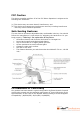
FCC Caution This device complies with Part 15 of the FCC Rules. Operation is subject to the following two conditions: (1) This device may not cause harmful interference, and (2) This device must accept any interference received, including interference that may cause undesired operation. Safe Seating Gestures The user have to choose an adjustable chair, comfortable is the key. You should follow the manufacturer’s instructions for adjusting the backrest to fit your body properly.
Chapter-1 Introduction Thank you for choosing the CNet Wireless series product. CWR-854 is an ideal Wireless-G Router for the small office or home networking environments. Setting SOHO and enterprise standard for high performance, secure, manageable and reliable WLAN. CWR-854 is not only a Wireless Router but also supports AP Client / Bridge and WDS (Wireless Distributed System) mode to satisfy all kinds of the application from different networking environment.
1.2 Specification Standard IEEE 802.11G/B Frequency Band 2.400GHz ~ 2.484GHz Radio Type IEEE 802.11g: OFDM (64-QAM, 16-QAM, QPSK, BPSK) IEEE 802.11b: DSSS (CCK/DQPSK/DBPSK) Data Rate (Wireless) 802.11g: 54 / 48 / 36 / 24 / 18 / 12 / 9 & 6Mbps 802.11b: 11 / 5.5 / 2 & 1 Mbps with auto-rate fall back Access Protocol CSMA/CA Number of Operation Channel Operation Mode Security 2.412~2.462GHz (Canada, FCC) / 11 Channels 2.412~2.484GHz (Japan, TELEC) / 14 Channels 2.412~2.
1.3 Features 802.11b/g compliant with 54Mbps high-speed data rate Operation modes: AP, AP client, Client, Bridge, WDS DHCP Server/Client Four Ethernet ports for broadband sharing Virtual DMZ, Port Forwarding Dynamic DNS TCP/UDP/ICMP/ARP protocol stack Firewall, URL/IP/Port/MAC filtering Wireless users access control Wireless security – 64/128bit WEP, WPA/WPA2, 802.1x and 802.
1.
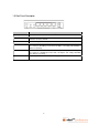
1.5 Real Panel Description Interfaces Description Antenna (Fixed / SMA) The Wireless LAN Antenna. Reset Push continually the reset button 5 ~ 10 seconds to reset the configuration parameters to factory defaults. WPS Push continually the WPS button 5 ~ 10 seconds to enable the WPS feature. LAN The RJ-45 sockets allow LAN connection through Category 5 cables. Supports auto-sensing on 10/100M speed and half / full duplex, and comply with IEEE 802.3 / 802.3u respectively.
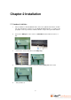
Chapter-2 Installation 2.1 Hardware Installation 1. Place the Wireless LAN Broadband Router to the best optimum transmission location. The best transmission location for your WLAN Broadband Router is usually at the geographic center of your wireless network, with line of sign to all of your mobile stations. 2. Connect the WAN port on the router to a Cable/DSL modem, Ethernet Server, or hub. 3. Connect one or more client PCs to the LAN port(s). 4.
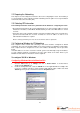
2.2 Preparing the Networking This chapter covers the things that need to be done before configuring the router. The first thing is to set all computers on the network for TCP/IP networking and also gather necessary information from the Internet Service Provider (ISP). 2.
3. Click the IP Address tab. Select Obtain an IP address automatically. 4. Now click the Gateway tab, and verify that the Installed Gateways field is Blank. Click the OK button. 5. Click the OK button again. Windows may ask for original Windows installation CD or additional files. Check for the files at c:\windows\options\cabs, or insert your Windows CD-ROM into the CDROM drive and enter the correct file location, e.g., D:\win98, D:\win9x, etc. ( “D” is the drive letter of the CD-ROM drive). 6.
Configuring Windows 2000 PCs 1. Click the Start button go to Settings and click on Control Panel. In Control Panel, double-click the Network and Dial-up Connections icon. 2. Select the Local Area Connection icon for the applicable Ethernet adapter (usually it is the first Local Area Connection listed). Double-click the Local Area Connection and Click the Properties button. 3. Make sure the box next to Internet Protocol (TCP/IP) is checked.
4. Select Obtain an IP address automatically and click the OK button. Click the OK button again to complete the PC configuration. 5. Restart your computer.
Configuring Windows XP PCs The following instructions assume you are running Windows XP with the default interface (Control Panel looks different then previous versions of Windows). If you are using the Classic View (where icons and menus look similar to previous Windows versions), please follow the instructions for Windows 2000. 1. Click the Start button and then the Control Panel icon. Click the Network and Internet Connections icon. Then click the Network Connections icon. 2.
4. Select Obtain an IP address automatically and click OK. Click the OK button again to complete the PC configuration.
Chapter-3 Web Configuration This chapter describes how to access the router through the web browser. Please be noted that in order to access the router’s admin page, a computer must be connected to one of the LAN ports on the router. The WLAN Broadband Router is delivered with the following factory default parameters on the Ethernet LAN interfaces. Default IP Address: 192.168.1.254 Default IP subnet mask: 255.255.255.0 WEB login User Name: WEB login Password: 3.
3.1.1.Operation Mode This page followed by Setup Wizard page to define the operation mode. CWR-854 supports three kinds of operation mode for the different application and environment. CWR-854 can be presented a NAT Router, Bridge or Wireless ISP Client.
3.1.2 Time Zone Settings Users can synchronize the local clock on the router to an available NTP server (optional). To complete this setting, enable NTP client update and select the correct Time Zone. Enable NTP client update: Enable time zone update function Time Zone Select: Select the time zone this router is used in. NTP server: Select from the list of NTP servers by clicking the down arrow key or manually enter time server IP address.
3.1.3 LAN Interface Setup In the LAN interface Setup page, users can change the LAN IP address and Subnet Mask of the router. Most Users will not need to change these values. IP Address: Current IP address of the Wireless-G Router, not WAN IP address. Subnet Mask: Current subnet mask for the Wireless-G Router, not WAN subnet mask address Cancel: To skip the current settings and jump to the Setup Wizard page. Back: To skip the current settings and go back to the last page.
3.1.4 WAN Interface Setup In this screen users must identify and configure the connection type used for connecting to their Internet Service Provider (ISP). WAN Access Type: CWR supports 4 kinds of access type to connect the ISP – Static IP, DHCP Client, PPPoE, PPTP. Cancel: To skip the current settings and jump to the Setup Wizard page. Back: To skip the current settings and go back to the last page. Next: Go to the next page.
3.1.5 Wireless Basic Settings In the Wireless Basic Settings page, users can configure the operating “Band” and “Mode” as well as “Network Type”, ” SSID”, “Channel Number” and if required MAC address cloning. Operating Band: 802.11B/G, 802.11G or 802.11B Operating Mode: AP, Client, WDS and AP+WDS. Network type: when operating mode is “Client” mode, users can select the network type as “infrastructure” or “Ad-hoc”.
3.1.6 Wireless Security Setup This page is used to configure wireless security. CWR-854 could support WEP, WPA and WPA2 Encryption key. Those encryption methods could prevent any unauthorized access to your wireless network. After all items are set, click on “Finished” button to save all the parameters you have set, and the router will reboot automatically.
3.2 Operation Mode This page is used to configure which mode wireless broadband router acts. Gateway: Traditional gateway configuration. It always connects to the Internet via ADSL/Cable Modem. LAN interface, WAN interface, Wireless interface, NAT and Firewall modules are applied to this mode Bridge: Each interface (LAN, WAN and Wireless) regards as bridge.
3.3 Wireless 3.3.1 Basic Settings The Wireless Basic Settings include Band, Mode, SSID, Channel Number and other wireless settings. Disable Wireless LAN Interface: The wireless interface will be disabled when checked. Band: This Wireless-G Router can support three RF band: 802.11B/G, 802.11G and 802.11B. Mode: This Wireless-G Router supports four operating modes: AP, client, WDS, and AP+WDS.
user when the router connect to a Root AP (When Universal Repeater Mode be enabled) Apply Changes: Click on “Apply Changes” to save changes and logout. Reset: Click on “Reset” to undo your changes.
3.3.2 Wireless Advanced Settings In Advanced Settings page, more 802.11 related parameters are tunable. Authentication Type: The router supports three kinds of the authentication typesOpen System, Shared Key, and Auto. Fragment Threshold: Fragmentation mechanism is used for improving the efficiency when traffic is high in the wireless network. If a wireless client often transmits large files, you can enter new Fragment Threshold value to split the packet.
maximum performance is desired. Broadcast SSID: When enabled allows all wireless stations to detect the SSID of this wireless router. IAPP: The Inter-Access Point Protocol (IAPP) can extend multi-vendor interoperability to the roaming function. 802.11g Protection: Is used to prevent packet collision and increase performance in wireless networks with both 802.11b (using CCK modulation) and 802.11g (using OFDM modulation) devices. WMM: The short of Wi-Fi Multi-Media.
3.3.3 Security Here users define the security type and level of the wireless network. Selecting different methods provides different levels of security. Please note that using any encryption may cause a significant degradation of data throughput on the wireless link. There are five Encryption types supported: “None”, “WEP”, “WPA (TKIP)”, ”WPA2(AES)”, and “WPA2 Mixed”. No Encryption Used Encryption: “None” means no encryption used. Users can enable 802.
WEP Encryption Encryption: “WEP” (Wired Equivalent Privacy) encryption type. Set WEP Key: Only active when “Use 802.1x Authentication” is not selected. Use 802.1x Authentication: When this feature is enabled, users need to enter parameters of the “RADIUS Server” and select the encryption key length to be “WEP 64bits” or “WEP 128bits”. Authentication RADIUS Server: RADIUS Server’s Port number, IP address and Password. Apply Changes: Click on “Apply Changes” to save the setting.
- Key Length: Choose either 64-bit or 128-bit. Key Format: Select Hexadecimal or ASCII . Default Tx Key: Select the default encryption Key (Key1 to Key4) being transmitted. Encryption Key 1: enter any key code for Encryption Key 1. Encryption Key 2: enter any key code for Encryption Key 2. Encryption Key 3: enter any key code for Encryption Key 3. Encryption Key 4: enter any key code for Encryption Key 4. Apply Changes: Click on “Apply Changes” to save settings. Close: To close this window.
- Encryption: “WPA” stands for Wi-Fi Protected Access. There are three encryption modes – TKIP, AES and Mixed. TKIP: Temporal Key Integrity Protocol. AES: Advanced Encryption Standard. Mixed: WPA2 Mixed mode operation permits the coexistence of WPA and WPA2 clients on a common SSID. WPA2 Mixed Mode is a Wi-Fi Certified feature. During WPA2 Mixed Mode, the Wireless-G Router advertises the encryption ciphers (TKIP, CCMP, other) that are available for use.
WPA Authentication Mode: There are two modes of WPA authentication Enterprise (RADIUS) and Personal (Pre-Shared Key). WPA Cipher Suite: There are two modes could be chose – TKIP and AES ( WPA2 Cipher Suite: There are two method could be chose – TKIP and AES RADIUS Server: When user chooses RADIUS authentication, there are three parameters for the RADIUS server to be set – Port, IP address and Password.
3.3.4 Access Control Access Control allows user to block or allow wireless clients to access this router. Users can select the access control mode, then add a new MAC address with a simple comment and click on “Apply Changes” to save the new addition. To delete a MAC address, select its corresponding checkbox under the Select column and click on “Delete Selected” button.
3.3.5 WDS Settings When selected in the Basic Settings page and enabled here, Wireless Distribution System (WDS) enables the router to be used as a wireless bridge. Two Wireless-G Routers in bridge mode can communicate with each other through their wireless interfaces. To accomplish this, all wireless routers should be set to the same channel and the MAC address of other AP / Routers should be entered in the table. Enable WDS: enable WDS function.
3.3.6 Site Survey The Wireless Site Survey tool will scan and display all available wireless networks. Click on “Refresh” to search/re-scan for available Wireless-G Router(s) or IBSS(s). If any Wireless-G Router or IBSS is found, select and click on connect to start a connection. Refresh: Click on “Refresh” button to renew and show the table. Connect: You can select any listed wireless network and then click on “Connect” button, to establish a connection. Help: To request help information.
3.3.7 WPS This page allows you to change the setting for WPS (Wi-Fi Protected Setup). Using this feature could let your wireless client automically syncronize it’s setting and connect to the Access Point in a minute without any hassle. CWR-854 could support both Self-PIN or PBC modes, or use the WPS button (at real panel) to easy enable the WPS function. Notes: About the WPS button that please refer to the “Real Panel Description”.
3.4 TCP / IP Settings Please follow the following instruction to build the network connection between the wireless router and your computers or network devices. 3.4.1 LAN Interface This page is used to configure the parameters for local area network that connects to the LAN ports of your WLAN Broadband Router. Here you may change the setting for IP address, subnet mask, DHCP, etc. IP Address: Fill in the IP address of LAN interfaces of this WLAN Access Point.
configuration setting. Reset: Click the Reset button to abort change and recover the previous configuration setting.
3.4.2 WAN Interface “WAN Interface Setup” allows users to select the WAN connection type and configure the parameters pertaining to the WAN interface. The four different access types supported on this router are: Static IP, DHCP Client, PPPoE and PPTP. Static IP This is the connection type used when users have a fixed IP address from their ISP. In this case the IP address, Subnet Mask, Default Gateway, Primary and Secondary DNS Server IPs should be acquired from the ISP.
response. Enable Web Server Access on WAN: Click the checkbox to enable web configuration from WAN side. Enable IPSec pass through on VPN connection: Click the checkbox to enable IPSec packet pass through. Enable PPTP pass through on VPN connection: Click the checkbox to enable PPTP packet pass through. Enable L2TP pass through on VPN connection: Click the checkbox to enable L2TP packet pass through. Apply Changes: Click on “Apply Changes” to save changes and logout.
DHCP Client The DHCP client also called "Dynamic IP address" is the mostly used connection type by cable broadband service providers. In this case the user will automatically receive all IP information from the service provider. WAN Access Type: DHCP Client connection type. Host Name: Fill in the host name of Host Name. The default value is empty. MTU Size: Fill in the MTU size of MTU Size. The default value is 1400.
configuration. Enable Ping Access on WAN: Click the checkbox to enable WAN ICMP response. Enable Web Server Access on WAN: Click the checkbox to enable web configuration from WAN side. Enable IPSec pass through on VPN connection: Click the checkbox to enable IPSec packet pass through. Enable PPTP pass through on VPN connection: Click the checkbox to enable PPTP packet pass through. Enable L2TP pass through on VPN connection: Click the checkbox to enable L2TP packet pass through.
PPPoE PPPoE stands for “Point-to-Point Protocol over Ethernet”. PPP is the technology used for dialup Internet access. PPPoE works similarly except it works over a network connection. In this connection type, users are required to enter their PPPoE username and password. Some ISPs also require a service name to be entered. Usually, it’s not needed to enter the IP/DNS addresses. However, if users have static IPs through PPPoE, then they will need to enter IP and DNS addresses ISP provides.
application is active to connect the Internet. Manual: the connection to the ISP is set manually. Idle Time: Only active only when Connect On Demand is selected. This is the time it takes for the router to disconnect from the ISP if no access request is received. MTU Size: MTU is the Maximum Transmission Unit. It specifies the largest packet size permitted for Internet transmission.
PPTP PPTP stands for “Point-to-Point Tunneling Protocol”. PPTP is used to join 2 networks using the Internet as an intermediary network. It allows you to connect your home and work network over the Internet. The key is to enter the PPPTP userID, password, and PPTP Gateway IP address. The IP addresses, subnet mask, and default gateway may or may not be required. WAN Access Type: PPTP connection type. IP Address: IP Address provided by ISP. Subnet Mask: Subnet Mask provided by ISP.
User Name: User Name provided by ISP. Password: Password provided by ISP MTU Size: MTU is the Maximum Transmission Unit. It specifies the largest packet size permitted for Internet transmission. Keep the default setting, 1452, to have the router select the best MTU for your Internet connection. Request MPPE Encryption: Click the checkbox to enable request MPPE encryption. Attain DNS Automatically: When enabled DNS is obtained automatically.
3.5 Firewall 3.5.1 Port Filtering When enabled packets are denied access to Internet/filtered based on their port address. Enable Port Filtering: Enable the Port Filtering function. Port Range: Enter the Port range (1 to 65535) that are to be blocked.. Protocol: Protocols to be blocked UDP, TCP or both. Comment: Allow user to add any comments for this port range. Apply Changes: Click on “Apply Changes” to save the settings. Reset: Click on “Reset” to undo your changes.
3.5.2 IP Filtering When enabled, LAN clients are blocked / filtered from accessing the Internet based on their IP addresses. Enable IP Filtering: Enable the IP Filtering function. Local IP Address: IP address that is to be blocked from accessing the Internet. Protocol: Select the protocol to be blocked UDP, TCP or both . Comment: This field is used for adding comments for each access control entry. Apply Changes: Click on “Apply Changes” to save the settings.
3.5.3 MAC Filtering When enabled, filtering will be based on the MAC address of LAN computers. Any computer with its MAC address on this list will be blocked from accessing the Internet. Enable MAC Filtering: Enable the MAC Filtering function. MAC Address: MAC Address that is to be blocked. Comment: Comments for this MAC Address. Apply Changes: Click on “Apply Changes” to save the setting. Reset: Click on “Reset” to undo your changes.
3.5.4 Port Forwarding The Port Forwarding feature allows users to create Virtual Servers by re-directing a particular range of service port numbers (from the WAN port) to a particular LAN IP address. Enable Port Forwarding: Enable port forwarding function. IP Address: This is the private IP of the server behind the NAT firewall. (Note: You need to give your LAN PC clients a fixed/static IP address for Port Forwarding to work properly.
3.5.5 URL Filtering URL Filtering is used to restrict users to access specific websites in internet. Enable URL Filtering: Enable URL Filtering function. URL Address: Add one URL address. Apply Changes: Click on “Apply Changes” to save the settings. Reset: Click on “Reset” to undo your changes. Delete Selected: Select and delete any of the listed rules in the Current Port Forwarding Table. Delete All: Delete all Port Forwarding settings in the Current Port Forwarding Table.
3.5.6 DMZ The DMZ feature allows one local user to be exposed to the Internet for special-purpose applications like Internet gaming or videoconferencing. When enabled, this feature opens all ports to a single station and hence renders that system exposed to intrusion from outside. The port forwarding feature is more secure because it only opens the ports required by that application.. Enable DMZ: Enable one PC to be exposed to the Internet.
3.6 Management 3.6.1 Status The status page provides a brief read-only report for system, LAN and WAN configuration information. The data displayed may be changed depending on your current configuration. System - Uptime: The date/time shows how long the router has been powered on. - Firmware Version: Show the current firmware version. Wireless Configuration - Mode: Shows the current operating modes. - Band: Shows the current operating band. - SSID: Shows the current SSID.
3.6.2 Statistics This page shows the packet counters for transmission and reception regarding to wireless, Ethernet LAN and Ethernet WAN networks. Wireless LAN - Sent Packet: It shows the statistic count of sent packets on the wireless LAN interface. - Received Packet: It shows the statistic count of received packets on the wireless LAN interface. Ethernet LAN - Sent Packet: It shows the statistic count of sent packets on the wireless LAN interface.
3.6.3 DDNS You can assign a fixed host and domain name to a dynamic Internet IP address. Each time the router boots up, it will re-register its domain-name-to-IP-address mapping with the DDNS service provider. This is the way Internet users can access the router through a domain name instead of its IP address. (Note: make sure that you have registered with a DDNS service provider before enabling this feature.) Enable DDNS: Enable DDNS function.
3.6.4 Time Zone Settings This wireless router provides a NTP (Network Time Protocol) client that can synchronize time with a configured NTP server. Pressing the Refresh Time button refreshes system timestamp and the Save/Time Sync buttons forces NTP client sync time with NTP server. Current Time: Show the current time and date of the router. Time Zone Select: Select the time zone of the country where this router is located. Enable NTP client update: Enable time zone update function.
3.6.5 Denial of Service (DoS Prevention) This page is used to enable and setup protection to prevent attack by hacker’s program. It provides more security for users. Enable DoS Prevention: Click the checkbox to enable DoS prevention. Whole System Flood / Per-Source IP Flood…: Enable and setup prevention in details. Select ALL: Click the checkbox to enable all prevention items. Clear ALL: Click the checkbox to disable all prevention items. Apply Changes: Click on “Apply Changes” to save settings.
3.6.6 Event Log This wireless router supports System Log information. This data is useful for monitoring and troubleshooting the network. Enable Log: Enable the Log function. System All: Show all log of wireless broadband router. Wireless: Only show wireless log. DoS: Only show denied of Service log Enable Remote Log: Enable the Remote Log function. Log Server IP Address: Enter the Remote Log Server IP address when you use the Remote Log function.
3.6.7 Upgrade Firmware The firmware on this wireless router can be easily upgraded. Firmware Upgrade: Click on the Browse button to select the firmware and then click on the Upload button. After the firmware upgrade is completed, the router will restart automatically. (Note: Do not power off the device while the firmware is being upgraded.) Select File: Enter the location and name of the file containing the new firmware. You can use the Browse button next to this field to browse for the file.
3.6.8 Save / Reload Settings Users can create a backup file that contains current router settings. This backup file can be used to restore router settings. This is specially useful in the event you need to reset the router to its default settings. Save Settings to File: Click on “Save” button to save the settings to a file “config.dat”. Load Settings from File: Enter the location and name “config.dat” of the file which was saved. You can use the “Browse” button to browse to the location of the file.
3.6.9 Password This page is used to set the account to access the web server of Access Point. Empty user name and password will disable the protection. User Name: Enter the new login user name. The user name can contain 1 to 30 characters and/or digits, and are case sensitive. (Note: if you empty the user name, the password login protection will be disabled.) New Password: Enter the new login password. The passwords can contain 1 to 30 characters and/or digits, and are case sensitive.
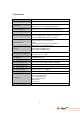
Appendix A: Troubleshooting Symptom Inability to access the router Possible Causes Things to Do • Incorrect or incompatible • Verify that the wireless wireless network configuration. network configurations For example, shared key between the wireless client authentication is configured on and wireless AP/Router are the wireless AP/Router and the compatible. Make sure that the wireless client is attempting client system’s network card is open system authentication set to receive IP automatically.
Intermittent connectivity • AP/Router is not power on • Check the “Power” LED. Make sure that you've plugged in the power cord. • IEEE 802.1X authentication is enabled on the wireless client and is not enabled on the wireless AP/Router • The symptom of this issue is when the wireless client loses connectivity every 3 minutes or so. Disable the authentication feature on the wireless client.
wireless radio button might be configured to start in the off position automatically. • A wireless network adapter driver failing in early stages of service startup may result in the Wireless Zero Configuration or Wireless Configuration service not initializing over that interface. Client can't connect to the AP/Router's configuration utility. • Wrong IP address 64 • Make sure that your PC is using an IP address within the correct range. It should be 192.168.1.2 to 192.168.1.254 for the default value.
Appendix B: Frequently Asked Questions Q1: What is wireless networking? Ans: The term wireless networking refers to the technology that enables two or more computers to communicate using standard network protocols, but without network cabling. Strictly speaking, any technology that does this could be called wireless networking. The current buzzword however generally refers to wireless LANs. This technology, fuelled by the emergence of cross-vendor industry standards such as IEEE 802.
Figure A2: Hardware Access Point. Wireless connected computers using a Hardware Access Point. Figure A3: Software Access Point. Wireless connected computers using a Software Access Point. Q3: Can I mix wireless equipment from different vendors? Ans: Because most wireless networking hardware vendors support the 802.11 standard they can inter operate.
also allow considerable flexibility in providing access to different network types, such as different types of Ethernet, Wireless and Token Ring networks. Such connections are only limited by the number of slots or interfaces in the computer used for this task. Further to this the software access point may include significant additional features such as shared Internet access, web caching or content filtering, providing significant benefits to users and administrators.
is analogous to Ethernet cabling, the answer to this question becomes clear. To share an Internet connection across a LAN you need two things: If your LAN is wireless, the same criteria apply. You need a hardware or software access point and a wireless LAN. Any computer equipped with a wireless network card running suitable Internet sharing software can be used as a software access point. (See Figure A8) A number of vendors offer hardware access points.
produces secure scrambled text. Decryption is the opposite of encryption; it is the mathematical operation that transforms cipher text to standard text. Q11: Why do I need a router? Ans: The increased reliance on computers to store valuable information and the development of applications that share information over the internet through networked personal computers, in combination with the advent of computer hacking, has made information and network security an important issue.
Q21: What is the maximum number of users the Access Point facilitates? Ans: It depends on the volume of data and may be less if many users create a large amount of network traffic. Q22: What is the maximum number of IP addresses that the Router will support? Ans: The Router will support up to 253 IP addresses. Q23: Where is the Router installed on the network? Ans: In a typical environment, the Router is installed between the cable/DSL modem and the LAN.