Legend Inline panel shower enclosure installation Instructions (400 Series) PATENTS PENDING 1 Legend Inline (hinged) 05-12-2015
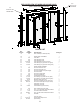
(D) ALWAYS ON INLINE SIDE EXPLODED VIEW OF MODULAR INLINE PANEL (RIGHT HAND HINGED SHOWN) (A) ALWAYS ON DOOR SIDE PARTS LIST K EY LE TTE R A PART NUMBER 404 DESCRIPTION WALL JAMB (door assembly side) QUANTITY 1 B b1 b2 b3 b4 b5 b6 ---235 404 405 6112PHS C 154 B C 532 B INLINE PANEL ASSEMBLY Panel Rails Panel Expander Jamb Panel Expander Jamb Panel Assembly Screws (not shown) Panel Glazing Vinyl (used with 1/8" glass) Panel Glazing Vinyl (used with 5/32" glass) 1 2 1 1 4 ----- C c1 c2 c3 c4 c5 c6 c
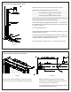
STEP 1 Position Door Assembly Side Wall Jamb Determine and mark the curb centerline as shown in figure 1. Decide which configuration best suits your needs door assembly on left / inline panel on right OR inline panel on left / door assembly on right Your choice (of door location above) will determine which wall you will attach the 404 Wall Jamb to (see exploded view). Position Wall Jamb (A) up against the shower wall . . . and center it on the centerline mark.
STEP 3 Install Door Assembly figure 3 Detail shows strike on wall side,see exploded view on sheet 2 also. Cartwheel the door assembly 180 degrees if you want the door to strike on the panel side. Lift Door Assembly (C) onto base ledge and over Vinyl Bushing (J2) installed in step 2 then slide Door Frame (C) into Wall Jamb (A) Once Door Assembly is positioned, always double check to make sure that door swings out. Leave door assembly standing as is temporarily and do not fasten at this time.
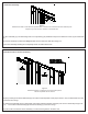
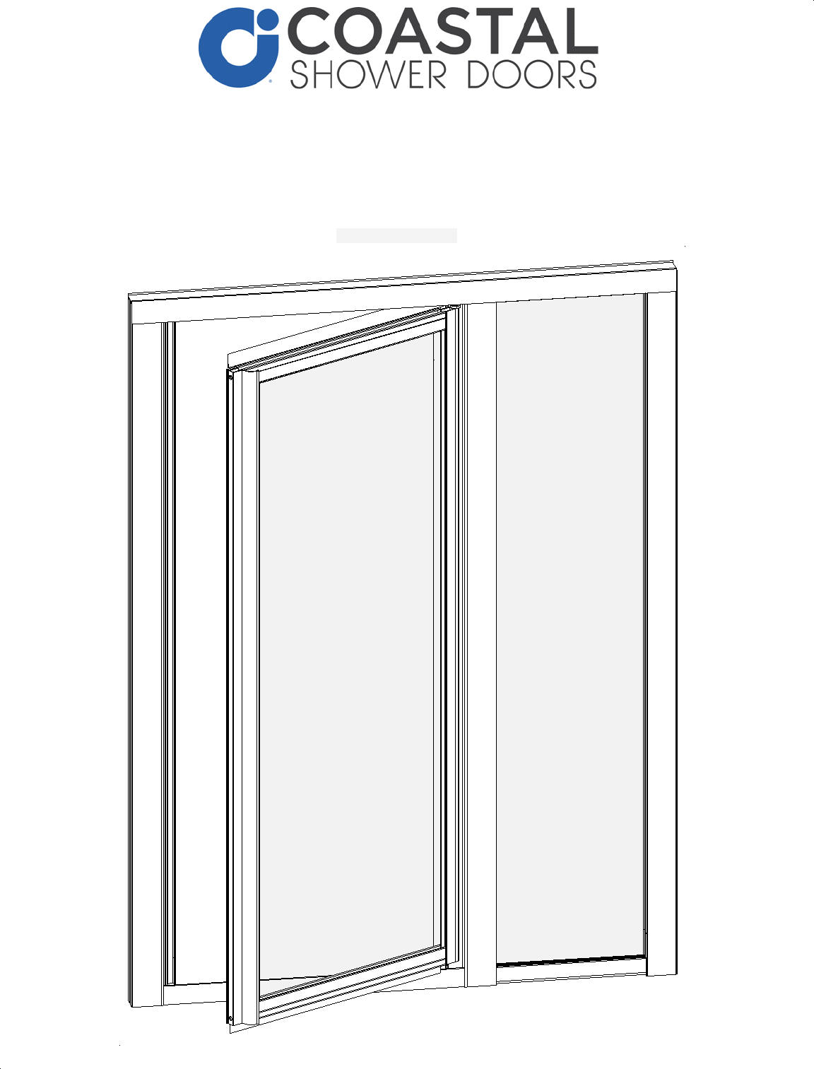
STEP 5 Insert Inline Panel Wall Jamb and Position Inline Panel figure 5 Door Frame Assembly (C) should be pushed up against Wall Jamb (A). Inline Panel Assebly (B) should in turn be pushed up against Door Frame Assembly (C). Step inside shower enclosure and push Wall Jamb (D) up against the shower wall as shown. Secure Wall Jamb (D) with three Installation Screws (E). Next, secure Wall Jamb (A) to Door Assembly (C) using three (3) Adjustment Screws (G).
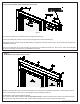
STEP 7 Attach (OPTIONAL) Travel Latch at Strike Side figure 7 Travel Latch is an optional piece and therefore does not come with all units. Before drilling a 1/8" hole required to attach the Travel Latch, position the Travel latch (9738N) as indicated in figure (with the base 1/16" from edge of the vertical post). Additionally, position it vertically centered or at a height that is comfortable for you to reach. Mark the hole location and drill a hole using a 1/8" drill bit. Attach Travel Latch as shown.