® 5030 A/E Rim Clamp® Tire Changer For servicing single piece automotive and most light truck tire/wheel assemblies. See RIM Safety page iv ÌOperating Instructions on page iv. Safety Set-up Operation Maintenance Instructions Instructions Instructions Instructions READ these instructions before placing unit in service. KEEP these and other materials delivered with the unit in a binder near the machine for ease of reference by supervisors and operators. 1601 J. P.
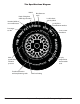
Tire Specifications Diagram Radial Rim diameter code Ratio of height to width (aspect ratio) RA AL DI DOT MA 3 5P SI MAX. PRESS. D OA BS 00L 13 AL EW L2 S 2XXXXX CORD PLIE WEAR 22 EAD TR MA X. L 0 TR A C T IO N M TE SID RE A ATU R PE M L9 A BC 03 6 Severe snow conditions PLIES 2XXXXX CO RD A Treadwear, traction and temperature grades ii • ELESS TUB MANUFACT U R TIRE N P D4 EA TR Max. permissible inflation pressure E 65R15 95H / 5 21 +S AM Passenger car tire U.S.
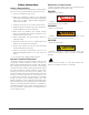
Safety Instructions Owner’s Responsibility To maintain machine and user safety, the responsibility of the owner is to read and follow these instructions: • Follow all installation instructions. • Make sure installation conforms to all applicable Local, State, and Federal Codes, Rules, and Regulations; such as State, Federal OSHA Regulations and Electrical Codes. • Carefully check the unit for correct initial function. • Read and follow the safety instructions.
Safety Notices and Decals Remember R.I.M. WARNING Failure to follow danger, warning, and caution instructions may lead to serious personal injury or death to operator or bystander or damage to property. Do not operate this machine until you read and understand all the dangers, warnings and cautions in this manual. For additional copies of either, or further information, contact: Hennessy Industries, Inc. 1601 JP Hennessy Drive LaVergne, TN 37086-3565 (615) 641-7533 or (800) 688-6359 www.ammcoats.
Table of Contents Tire Specifications Diagram..................................... ii Custom and Special Wheels .................................. 16 Safety Instructions .................................................. iii Tube Type Tires ........................................................ 16 Owner’s Responsibility............................................ iii Maintenance Instructions ............................... 17 - 18 Operator Protective Equipment ...............................
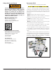
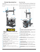
Principal Operating Parts Do It Now! Now is a good time to contact product service to start warranty, otherwise warranty starts at time of shipment. Know Your Unit Compare this illustration with the unit before placing it into service. Maximum performance and safety will be obtained only when all persons using the unit are fully trained in its parts and operation. Each user should learn the function and location, of all controls.
Operating Instructions The unit must be properly operated and properly maintained to help avoid accidents that could damage the unit and injure the operator or bystanders. This section of the Operating Instructions manual review basic operations and use of controls. These instructions should be reviewed with all employees before they are allowed to work with the machine. Keep these instructions near the machine for easy reference.
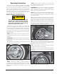
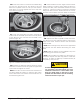
5. Determine the mounting side of the wheel. The mounting side is the narrow side of the drop center. (Tire removed in Figure 4 for clarity.) 8. The mount/demount tool roller should be in contact with the rim edge. Turn the swing arm adjusting knob to move the tool away from the rim 1/8 to 1/4 inch. Narrow Side Drop Center Long Side Figure 4 - Determining Mounting Side of Wheel 6. Place tire/wheel assembly on table top with mounting side up (Figure 5).
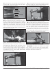
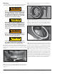
10. Insert the smooth curved end of the bead lifting tool over the forward end of the demount tool and below the top bead of the tire. Use your free hand to press down on the tire opposite the tool to help with tool insertion (Figure 9). 13. Lift and hold the tire at an angle so that the lower bead is resting in the drop center directly across from the demount tool, and is loose below the demount tool (Figure 11).
Mounting This information must be read and followed carefully to prevent accidents and injuries during mounting. 3. Lubricate tire beads liberally with tire manufacturer approved lubricant (Figure 13). WARNING Check tire and wheel carefully before mounting. Make sure the tire bead diameter and wheel diameter match exactly. Consult the Rubber Manufacturer’s Association for approved rim widths for tire sizes. Mismatched tires and wheels explode.
WARNING Do not force the tire onto the rim. Bead damage could result making the tire unsafe and/ or creating the risk of injury. NOTE: The clip-on chuck on the end of the hose should always be an open style with all parts in proper working order. Tire Pressure Tire Inflation Tire Inflation NOTE: If table top rotation stalls, reverse the table top momentarily until the tire bead is again loose on the wheel.
Bead Sealing Bead Seating 1. Connect the inflation hose to the tire valve stem. Hold the tire up against the upper edge of the wheel. Be sure the top bead of the tire is over the bottom of the valve stem (Figure 15). WARNING Operator should keep hands, arms, and entire body away from the tire during the remaining bead seat and inflation procedures. Do not stand over tire, as personal injury could result. WARNING Figure 15 - Lift Tire Upwards for Bead Sealing 2.
Inflation DANGER NEVER exceed tire manufacturer’s recommended air pressure. Tires can explode, especially if inflated beyond these limits. Keep hands, arms, and entire body back from inflating tire. Avoid distraction during inflation. Check tire pressure frequently to avoid over inflation. Excessive pressure can cause tires to explode, causing serious injury or death to operator or bystander. 1. Make sure both beads are seated. When both beads are seated, the tire is ready for inflation. 2.
Stages of Inflation on a Conventional Tire and Rim Review these descriptions and diagrams carefully. Refer to them as necessary during bead sealing, bead seating, and inflation to verify that you are proceeding properly and safely. Bead Sealing Bead sealing is the process of capturing air pressure between the tire and the rim. The tire will usually contain about 1/2 to 2 PSI at initial bead seal.
Mismatched Tires and Wheels Never mount and inflate mis-matched tires and wheels. DANGER Mismatched tire and wheel combinations will explode, if you attempt to force a bead seat, causing personal injury or death to operator and/or bystanders. Important: Always read and follow operating instructions.
Automobile Performance, Custom and Aluminum Wheels CAUTION Only tire technicians with experience and training on custom wheels should attempt to service expensive custom alloy or aluminum wheels and high-performance lowprofile tires. Pre-Operation Notes: • Ensure all weights have been removed. • Assistance will be required on wide wheels. • Clamp wheel from the outside. • Use ample lubricant for mount and demounting • Always review wheel nicks and/or scratches with the owner before servicing.
NOTE: Some wheels have a low pressure sensor/ transmitter strapped to the wheel. This is especially true on run-flat tire/wheel systems. The sensor is positioned directly opposite from the valve stem. To avoid damaging the sensor, always loosen the top bead at the valve stem first, then loosen the bottom bead at the valve stem, and then continue to loosen the remaining circumference of the beads as necessary (Figure 20). 6. Lubricate upper bead liberally.
9. Hold lifting tool in place and depress the table top control pedal momentarily to jog the wheel a short distance. Performance Tires and Wheels - Mounting 1. Lubricate both tire beads liberally. Performance tires will require more lubrication than standard passenger car tires. 2. Mount the lower bead. In most cases, the lower bead will mount easily. Figure 26 - Pull Lifting Tool Down and Rotate Wheel 10. The lifting tool can usually be removed after jogging the wheel a short distance.
4. Mount the top bead using short rotations of the wheel. As the wheel progresses, a second drop center tool should be added to keep the bead in the drop center. Figure 31 - Add Second Drop Center Tool 5. On extremely tight tire and wheel combinations, it may be necessary to use the hooked end of the bead lifting tool to flip the tire over the rim flange (Figure 32). Figure 32 - Use Hooked End of Bead Lifting Tool 6.
Custom and Special Wheels Tube Type Tires Mounting CAUTION 1. Avoid pinching or forcing the tube. Only tire technicians with experience and training on custom wheels should attempt to service expensive custom alloy or aluminum wheels and high-performance lowprofile tires. 2. Apply rubber lubricant to the beads of the tire. 3. Mount the bottom bead. 4. Round out the tube with a small amount of air. 5. Apply rubber lubricant to the tube. 6. Insert the tube into the tire.
Maintenance Instructions Read and follow all the maintenance instructions provided in this manual to keep the machine in good operating condition. Refer to the other materials received with the unit and to the service bulletins from the manufacturer for additional instructions on proper maintenance and service. Regular inspections and proper maintenance are essential to preventing accidents and injuries.
Duckhead (Mount/Demount Tool) Adjustment To Adjust Tool Head Lift Shoulder screw (ref.1) sets the tool head lift for metal duckhead mount/demount tools – no adjustment required. Place shim 85606345 on screw if using a plastic duckhead mount/demount tool. To Adjust Lock Tightness With lock handle unlocked, loosen jam nut (ref. 3) and adjust pin (ref. 4) until a slight firmness is obtained, then tighten jam nut and check. Also recheck tool head lift at this time.
Setup Instructions CAUTION Proper unit installation is necessary for safe use and efficient operation. Proper installation also helps protect the unit from damage and makes service easier. Always place safety poster and instructions near the unit. Location Select a location using the drawings below. The area should provide the operator with enough space to use the equipment in a safe manner. The area selected should be well lit, easy to clean and should be away from oil, grease, brake lathe chips, etc.
ONE WORD FOR SAFETY R.I.M. READ INSPECT MOUNT READ… Mounting and inflating the wrong size tire can get you hurt. Read the size on the tire and make sure it matches the rim. Be especially careful about putting a smaller tire on a larger rim, such as a 16-inch tire on a 16.5-inch rim. Inflation of a mismatched tire and rim can cause an explosion. INSPECT… Before you put any tire on a rim, inspect the rim for rust, tough spots, bent edges, or cracks that could prevent the tire from seating right.