® 6050 A/E 6050 AX/EX Rim Clamp® Tire Changer For servicing single piece automotive and most light truck tire/wheel assemblies Safety Instructions Operating Instructions Installation Instructions Maintenance Instructions READ these instructions before placing unit in service. KEEP these and other materials delivered with the unit in a binder near the machine for ease of reference by supervisors and operators. 1601 J. P.
Table of Contents Operator Protective Equipment Definitions of Hazard Levels ................................1 Owner’s Responsibility ........................................1 Principal Operating Parts .....................................2 Operating Instructions .........................................3 Bead Loosening and Demounting ....................3 Mounting ...........................................................6 Inflation ..................................................................
Definitions of Hazard Levels Owner’s Responsibility Identify the hazard levels used in this manual with the following definitions and signal words: DANGER Watch for this symbol: To maintain machine and user safety, the responsibility of the owner is to read and follow these instructions: • Follow all installation instructions. DANGER It Means: Immediate hazards which will result in severe personal injury or death.
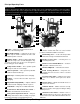
Principal Operating Parts Know Your Unit Compare this illustration with the unit before placing it into service. Maximum performance and safety will be obtained only when all persons using the unit are fully trained in its parts and operation. Each user should learn the function and location of all controls. Prevent accidents and injuries by ensuring the unit is properly installed, operated, and maintained.
Operating Instructions The unit must be properly operated and properly maintained to help avoid accidents that could damage the unit and injure the operator or bystanders. This section of the Operating Instructions manual review basic operations and use of controls. These instructions should be reviewed with all employees before they are allowed to work with the machine. Keep these instructions near the machine for easy reference.
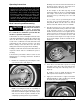
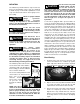
5. Determine the mounting side of the wheel. The mounting side is the narrow side of the drop center. (Tire removed in Figure 4 for clarity.) 8. The mount/demount head roller should be in contact with the rim edge. Turn the swing arm adjusting knob to move the roller away from the rim 1/8 to 1/4 inch (Figure 7). Narrow Side Drop Center Long Side Figure 4 – Determining Mounting Side of Wheel 6. Place tire/wheel assembly on table top with mounting side up (Figure 5).
10. Insert the smooth curved end of the bead lifting tool over the forward end of the demount head and below the top bead of the tire. Use your free hand to press down on the tire opposite the head to help with tool insertion (Figure 9). Figure 11 - Demounting Lower Bead 14. Depress the table top pedal to rotate the wheel. The demount head will guide the bead up and over the edge of the wheel. Continue rotation until lower bead is demounted. Figure 9 - Insert Bead Lifting Tool 11.
Mounting This information must be read and followed carefully to prevent accidents and injuries during mounting. Check tire and wheel carefully before mounting. Make sure tire bead diameter and wheel diameter match exactly. Consult the Rubber Manufacturers Association's charts or The Tire Guide for approved rim widths for tire sizes (contact information included with Table of Contents). 4. Place tire over wheel and move swing arm into position.
INFLATION Tire inflation is performed in three steps: bead seal, bead seat, and inflation. These steps are explained in detail on page 13. Read the explanation of each step and understand them thoroughly before proceeding. Check for proper inflation gauge operation. Accurate pressure readings are important to safe tire inflation. Refer to the Operating Maintenance section of this manual for instructions.
T. If tire and wheel are properly lubricated and operator cannot achieve bead seal after 3 or 4 attempts, the valve core may be removed from the valve stem to allow more air flow into the tire to assist with bead seal. After bead seal is achieved, remove the chuck and reinstall the valve core. Bead Seating Operator should always stand behind Inflation Guard and keep hands, arms, and entire body away from the tire during the remaining bead seat and inflation procedures.
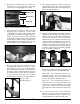
Use position 2 only on large diameter wheels. This provides outside clamping of wheels 14 to 21 inches, and inside clamping of wheels from 16 to 24 inches in diameter. se ea el lR ua an M Position 1 e lv Va Figure 18 - Location of Manual Release Valve Position 2 Performance, Custom, and Aluminium Wheels Only tire technicians with experience and training on custom wheels should attempt to service expensive custom alloy or aluminum wheels and high-performance lowprofile tires.
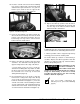
AD: Wheels with an asymmetrical hump have a larger "ledge" type hump around the wheel except at the valve hole making them more difficult to mount and demount (Figure 22). Ledge Hump Rest of Wheel Smooth Hump At Valve Hole Figure 25 - Lubricate Bottom Bead 5. Clamp the wheel to the table top as described in items AB and AC on page 9. Always clamp custom wheels from the outside. Figure 22 - Asymmetrical Hump Wheel AE: Some wheels have a low pressure sensor/transmitter strapped to the wheel.
r Senso Figure 28 - Insert Bead Lifting Tool (Optional Drop Center Tools Shown) 9. Hold lifting tool in place and depress the table top control pedal momentarily to jog the wheel a short distance. Check the wheel and tire to verify that operation is not causing damage. Figure 31 - Use Help on Lower Bead, Watch Sensor Performance Tires and Wheels - Mounting 1. Lubricate both tire beads liberally. Performance tires will require more lubrication than standard passenger car tires. 2. Mount the lower bead.
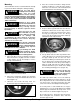
4. Mount the top bead using short rotations of the wheel. On stiff sidewall tires, add a second drop center tool to keep the bead in the drop center. European Performance Wheels (Asymmetrical Hump) Some European wheels have very large humps except near the valve hole. On these wheels, the beads should be loosened at the valve hole on both the upper and lower sides first (Figure 37).
Stages of Inflation Review these descriptions and diagrams carefully. Refer to them as necessary during bead sealing, bead seating, and inflation to verify that you are proceeding properly and safely. Bead Sealing A 140 PSI air blast from the table top jets creates an air curtain to aid in bead sealing. Never exceed 10 PSI in the tire during bead sealing. The tire will contain about 1/2 to 2 PSI when bead seal is obtained.
Maintenance Instructions Read and follow all the maintenance instructions provided in this manual to keep the machine in good operating condition. Refer to the other materials received with the unit and to the service bulletins from the manufacturer for additional instructions on proper maintenance and service. Regular inspections and proper maintenance are essential to preventing accidents and injuries.
Separator/Lubricator Maintenance Check oil and water levels regularly, and perform these maintenance items weekly: Check operation of the pressure limiter as shown and described below at least monthly: A. Disconnect air supply to machine. 2. Connect the inflation hose to an empty service tank with a pressure gauge (gauge should read 0). Use a tank with a 250 PSI pressure rating. B. Drain water from the separator by unscrewing the petcock on the bottom of bowl.
Installation Instructions Proper unit installation is necessary for safe use and efficient operation. Proper installation also helps protect the unit from damage and makes service easier. Always place safety poster and instructions near the unit. CAUTION Location Select a location using the drawings below. The area should provide the operator with enough space to use the equipment in a safe manner.
Notes COATS 6050A/AX/EX Rim Clamp Tire Changer • 17
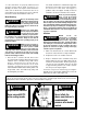
ONE WORD FOR SAFETY R.I.M. READ INSPECT MOUNT READ… INSPECT… MOUNT… Mounting and inflating the wrong size tire can get you hurt. Read the size on the tire and make sure it matches the rim. Be especially careful about putting a smaller tire on a larger rim, such as a 16-inch tire on a 16.5-inch rim. Before you put any tire on a rim, inspect the rim for rust, tough spots, bent edges, or cracks that could prevent the tire from seating right.