
Operating instructions


CPS:Doc 20017 V1 24/01/2012 Page 12 Issue 1 24/01/2012
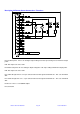
Description Of Remote Switching and Power control
Remote RF ON
Remote Output set
Pin 5 RF On/Off. To enable this function connect pin 10 to a ground pin. To enable RF connect pin 5 to a
ground pin, via a switch, transistor or relay. This is not latching, grounding pin 5 will switch RF On, and
removing this ground will switch RF Off.
N.B. Interlock functions will operate normally when using this function.
Pin 15 Remote RF On/Off Switch Enable. Ground this pin to enable the remote RF On/Off control
function, when it is enabled the remote indicator on the front panel is illuminated.
Pins 1,2 Remote power set. To enable this function connect pin 17 to a ground pin. The set-point or
control is a positive voltage in the range 0v to 5v. 0 volts gives zero output power and 5 volts gives
maximum output power.
Pin 17 Remote RF setpoint enable. Ground this pin to enable the remote setpoint control, when it is
enabled the remote indicator on the front panel is illuminated.
Pin 21 True power control enable. Ground this pin to enable “True power” operation. Note this should not
be selected at the same time as remote feedback. When true power is selected the controller
compensates for reflected power by raising the set power.
Pins 7,8 Ground