Document Number DS000034 User Manual NETNode Phase 1 and 2 Units (software versions >V2.
NETNode Phase 1 and 2 Units NETNode User Manual 0. Preface 0.1. About this Document This manual describes the operation of domo IP radio MESH systems. The manual is divided into three main sections. Getting started and basic operation This section describes to users how to deploy and use a domo IP Radio MESH system with its associated NETNode units in typical operational scenarios.
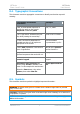
NETNode Phase 1 and 2 Units NETNode User Manual 0.4. Typographic Conventions This document uses these typographic conventions to identify text that has a special meaning: Typographic Conventions Convention Examples TEXT in small capitals represents a specific key press on the console keyboard or hardware panel. ESC, F1, SHIFT The + sign means “hold down the first key while pressing the second key”.
NETNode Phase 1 and 2 Units NETNode User Manual 0.6. Trademarks All trademarks or registered trademarks that appear in this document are the property of their respective owners. 0.7. Related Documents You may also need to read: Document Source None 0.8. Document History This document was written and produced by Cobham Technical Communications Team. This is a change controlled document. Each main page of this document displays a file name at the bottom left corner of the page.
NETNode Phase 1 and 2 Units NETNode User Manual Contents 0. Preface ......................................................................................... i 0.1. 0.2. 0.3. 0.4. 0.5. 0.6. 0.7. 0.8. About this Document ........................................................................................ i Who Should Read this Book............................................................................... i Assumed Knowledge .........................................................................
NETNode Phase 1 and 2 Units NETNode User Manual 3.1.1. Connecting the Antennas ...................................................................... 2-24 3.1.2. Connecting to AC Supply ....................................................................... 2-24 3.1.3. Connection to DC Supply – Mesh Phase 1 & Phase 2 Robust Unit.............. 2-24 3.2. Starting Up and Shutting Down the NETNodes .............................................. 2-25 3.2.1. Powering up the NETNodes ............................
NETNode Phase 1 and 2 Units NETNode User Manual 4.4.8. IP Address ........................................................................................... 2-47 4.4.9. Network Mask ...................................................................................... 2-48 4.4.10. Gateway .............................................................................................. 2-48 4.4.11. Update All Nodes .................................................................................. 2-48 4.4.
NETNode Phase 1 and 2 Units 4.13.4. 4.13.5. NETNode User Manual Scrambling ........................................................................................... 2-64 Scrambling Key .................................................................................... 2-65 5. Streaming over IP ....................................................................5-66 5.1. General Info............................................................................................... 5-66 5.2.
NETNode Phase 1 and 2 Units 12. Connector Pin Outs (Phase 2 Plain Box) ................................ 12-89 12.1. 12.2. 12.3. 12.4. 12.5. 12.6. 12.7. 13. NETNode User Manual AV - 4-pin 0B LEMO Socket (TX and RX) ..................................................... 12-89 Data - 3-pin 0B LEMO Socket..................................................................... 12-89 Aux 15-way Female High Density D-Type ................................................... 12-90 RJ45 1 and 2.....................
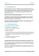
NETNode Phase 1 and 2 Units NETNode User Manual 1. Introduction Cobham Surveillance domo has been supplying point to point high data rate digital video links for many years to security users. These links exhibit exceptional performance, enabling users to reliably exchange video data in extremely difficult RF transmission environments such as mobile links and links in dense urban areas.
NETNode Phase 1 and 2 Units NETNode User Manual 1.2.
NETNode Phase 1 and 2 Units NETNode User Manual 2. Getting Started and Basic Operation 2.1. Which Model do I Have? Each unit in the domo product range is marked with two panels. Product Code Panel. Give product code and manufacturers information. CE and Serial Number Panel. Gives CE mark and product serial number. domo NETNode1W-217250 Made in the UK Mesh systems are available in 3 different product enclosures. These enclosures are targeted to different user applications.
NETNode Phase 1 and 2 Units NETNode User Manual 2.2. Phase 1 Unit The domo product code can be referenced in the table below. Product Code Product Accompanying items NETNode1W-217250 1W RF output Cables: (2.17 to 2.50GHz) MESH link 1-off Control 2m (CA288) (1 node) 1-off DC Power 5m (CA285) 1-off Ethernet 5m (CA284) CD with operating software and manual NETNode1W-550600 1W RF output Cables: (5.5 to 6.
NETNode Phase 1 and 2 Units NETNode User Manual NETNode Note: Antennas are not included with this product. 2.3. Phase 2 Products 2.3.1. Plain Box Variant The domo product code can be referenced in the table below. Product Code Product Accompanying items NETNode-P-217250 1W RF output Cables: (2.17 to 2.50GHz) MESH link 1-off Control 2m (CA0001) (1 node) 1-off DC Power brick (CA0023) 1-off Auxiliary cable(CA0474) NETNode-P-115140 NETNode-V2.
NETNode Phase 1 and 2 Units (1.15 to 1.40GHz) NETNode User Manual MESH link As NetNode-P-217250 (1 node) NETNode-P-034047 1W RF output Cables: (340 to 470MHz) MESH link As NetNode-P-217250 (1 node) NETNode-P-440500 1W RF output Cables: (4.40 to 5.00GHz) MESH link As NetNode-P-217250 (1 node) NETNode-AVI-UP2 Audio/Video Input option for Phase 2 Fitted inside the NETNode Cables: 1-off A/V cable 2m (CA0122) Note: Antennas are not included with this product. 2.3.2.
NETNode Phase 1 and 2 Units NETNode User Manual NETNode-R-115140 1W RF output Cables: (1.15 to 1.40GHz) MESH link As NetNode-R-217250 (1 node) NETNode-R-034047 1W RF output Cables: (340 to 470MHz) MESH link As NetNode-R-217250 (1 node) NETNode-R-440500 1W RF output Cables: (4.40 to 5.
NETNode Phase 1 and 2 Units NETNode User Manual The nodes are able to seamlessly connect into the network without user intervention. The only key parameters that need to be preloaded into the units are the encryption keys and the frequency. NETNode-V2.
NETNode Phase 1 and 2 Units NETNode User Manual Mesh could also be used to quickly deploy a multiple node surveillance system around an area of interest. The NETNode units could be used to contribute Video or IP data such as stills photography or sensor data.
NETNode Phase 1 and 2 Units NETNode User Manual The MESH can also be used to facilitate range extension. Nodes can communicate through a chain. Node 1 Node 2 Node 3 Node 4 In this example the MESH system is used to provide a video link back through a chain to a command vehicle. Using either the Talkback feature (Phase 2 NETNodes) or an external VOIP codec all the operatives could also be listening and communicating over the network. NETNode-V2.
NETNode Phase 1 and 2 Units NETNode User Manual 2.5. Getting Started on the Bench (Phase 1 Unit) 2.5.1. Cables and Connections This section describes how to connect the following domo model numbers. NETNodeIP1W-217250 (2.17 to 2.50GHz) NETNode-AVI-UP (option) The pictures below show the Phase1 domo NETNode product.
NETNode Phase 1 and 2 Units NETNode User Manual A domo MESH Phase 2 Weatherproof NETNode is supplied with the following cables: IP via Ethernet x 1 and DC Power is combined Part Number CA0403 Control 2m x1 Part Number CA0406 AV 2m x1 (if the NET-AVI-UP2R option is ordered) Part Number CA0477 A domo MESH Phase 2 Plain NETNode is supplied with the following cables: Standard 12V Power Block Part Number CA0023 Control cable 2m x1 Part Number CA0001 Special Control / Data Cable Part numb
NETNode Phase 1 and 2 Units NETNode User Manual 2. Now, connect the RS232 D-Type 9-way plug (f) to your computer‟s RS232 9-way jack (m). Caution: There are two D-Type 9-way plugs on the CA0288-5 cable – ensure you select the RS232 version by checking the label attached to the shell of the plug. The other is RS485. On a Phase 2 Robust Unit 3. Connect the Amphenol plug (m) from CA0406 cable to the Amphenol jack (f) on the NETNode labelled CTRL/DATA. 4.
NETNode Phase 1 and 2 Units NETNode User Manual Select Ethernet or RS232 IP address of any unit on the Network To set the IP address via RS232 select the correct PC RS232 port from the tools->network setting menu. If the NETNode unit is connected to a network that supports DHCP then leave the DHCP option box checked. If the network does not support DHCP then a valid static IP address must be entered and the DHCP box unchecked. Note: Click „Apply‟ after changing any configuration setting NETNode-V2.
NETNode Phase 1 and 2 Units NETNode User Manual Once a valid IP address is set it may also be changed in the WEB browser. Now that the IP address is established the web-server should be used to configure frequency and output power. Once the node is on the User network any Web-browser can be used to browse to the Mesh NETNode to configure and control the node or to browse network status. The unit can be browsed by entering the relevant IP address in the web-browser. 2.6.3.
NETNode Phase 1 and 2 Units NETNode User Manual 2.7. Web-browser Username and Password The web-browser will prompt for a Username and Password on the first connection. Username should be left blank The default password is „meshweb‟ The status page will be displayed upon successfully entering the Username and Password. Navigate to the Configuration page by clicking the Configuration Tab. NETNode-V2.
NETNode Phase 1 and 2 Units NETNode User Manual Mesh ID Set Output level select to „Low‟ and set Enable „ON‟ by „ticking‟ the check box. Note: Click „Apply‟ after changing any configuration setting Check that the Frequency is valid for the operation of the unit – specific country regulations will determine the frequencies available for operation. Note that 2400 to 2480MHz is licence exempt in most of the world. For the units to function in a single network the following must be set correctly: 1.
NETNode Phase 1 and 2 Units NETNode User Manual Power down the Unit. Repeat the procedure for a second node – making sure that the frequency is always set to be identical. Domo suggests configuring the system on the bench as outlined below. Mesh Node Power IP Mesh Node Power IP Private Network 12 Volts 12 Volts BEFORE SWITCHING ON THE WHOLE SYSTEM PLEASE NOTE: The DC power must be set to 12.5V and assume up to 2.5A current draw.
NETNode Phase 1 and 2 Units NETNode User Manual 2.9. Ethernet Locate, push and twist to lock the Amphenol connector into the socket labelled „IP‟, taking care to align the connectors. When using a plain box Mesh Node simply insert a RJ45 network cable into one of the 2 RJ45 Ethernet sockets. 2.10. Talkback audio (Phase 2 units only) Connect headset to T/B 6-way Lemo. Microphone power is provided on the audio connectors at approximately 3V (suitable for Electret microphones) 2.11.
NETNode Phase 1 and 2 Units NETNode User Manual 2.12. Antennas Note: It is important only to power up the NETNode unit with the Antennas fitted. Both antennas must be connected for normal operation. The units are supplied with different types of panel mounted connectors. The phase 1 units are supplied with panel mounted TNC connectors which carries the RF input and output. The antenna should be connected by screwing it onto the TNC, but care should be taken to not over tighten the connector.
NETNode Phase 1 and 2 Units NETNode User Manual The optimum choice of antenna will vary according to application. The following table gives some suggestions for suitable transmit antennas with the associated domo part number. Application Antenna model number Mobile body worn application 1.00 to 1.40GHz - ANTBCL 2.28 to 2.50GHz - ANTBCS Mobile vehicle application 1.00 to 1.40GHz – ANT4L 2.20 to 2.50GHz - ANT4S 5.60 to 5.90GHz – ANT4-560590 Long range point to point link 1.00 to 1.40GHz – ANT12L 2.
NETNode Phase 1 and 2 Units 2.13.4. NETNode User Manual Diversity and Antenna Positioning The domo MESH NETNode product uses an advanced diversity technique called maximum ratio combining to construct a good spectrum from two potentially damaged received signals. This requires a small separation of the antennas. Sometimes better results can be achieved by separating the antennas further.
NETNode Phase 1 and 2 Units NETNode User Manual 2.14. Battery / DC Power Considerations The Phase 1 MESH NETNode units can consume over 2A of current at 12V. Phase 2 NETNodes typically do not exceed 1.5Amps of current consumption at 12V nominal supply voltage. They are designed to trip off at 10.5V and reset on at 11.5V. The DC cable supplied as standard with the MESH node is 5m long to allow a customer to mount the NetNode on a mast. This suffers about 0.5V drop through the cable.
NETNode Phase 1 and 2 Units NETNode User Manual 3. Operation This chapter covers normal day to day operations of a fully configured NETNode system. If you are working with a new system or you need to change any of the configurations, look at the Advanced Procedures later in this guide. 3.1. Connecting Up the NETNode 3.1.1. Connecting the Antennas You‟ll need a NETNode and two antennas. 1. Connect both antennas to the RF connectors on the rear of the unit.
NETNode Phase 1 and 2 Units NETNode User Manual 3.2. Starting Up and Shutting Down the NETNodes 3.2.1. Powering up the NETNodes You‟ll need at least two fully configured NETNodes. (If they are not, then see advanced procedures). 1. Connect the live power cable to the NETNodes. 2. On the front panel, the Power LED will show solid green. 3. Do Nothing! - Leave the system to form a mesh automatically. 4. After about 5s on the front panel, the RF Connected LED will show solid green on each NETNode.
NETNode Phase 1 and 2 Units NETNode User Manual 3.3. Basic Operation 1. Start your web browser (normally: start internet). Note: You can use many different types of web browser with our products like Firefox for example. These web browsers start in slightly different ways. 2. Type the IP address of the NETNode you are connected to in the address bar. 3. Press ENTER on your keyboard 4. The Connect to dialog will open Leave blank Password is meshweb 5. Do not type a User Name 6.
NETNode Phase 1 and 2 Units NETNode User Manual 8. Click on the Configuration tab 9. Click on configuration 1 (it will show green when selected, like below) 10. In the Transmitter pane check the Enable check box. 11. In the Transmitter pane type in the frequency you want. 12. In the Mesh pane type in a Mesh ID (the number must be between 001 and 255) NETNode-V2.
NETNode Phase 1 and 2 Units NETNode User Manual 13. In the Mesh Pane type the Node ID (0 to 11) 14. Click the Apply button. You‟ll see the Configuration dialog appear. The NETNode is now configured and ready to form a part of a mesh. 3.3.1. About Enable Check Box This simply turns on the transmitter when checked. The transmitter only sends when it has data ready to move. For a unit to function in a mesh the transmitter must be enabled. 3.3.2.
NETNode Phase 1 and 2 Units NETNode User Manual 3.4. Connecting an IP Device to a NETNode Now you can attach an IP device to any of the NETNodes. There are many types of IP device you can attach: Computers IP Cameras Let‟s take the example of attaching a laptop computer to a NETNode. You might use this as an observation post to look at all the assets you have deployed on other NETNodes like cameras and microphones.
NETNode Phase 1 and 2 Units NETNode User Manual 3.5. Connecting a Second IP Device to a NETNode We have seen how to connect IP devices to the NETNodes using the Amphenol 4-way jack on the NETNodes labelled IP. In fact, you can connect a second IP interface to the same NETNode at the same time. Here‟s how! On a Phase 1 Unit You‟ll also need for the second IP device (an IP camera for example) a CA0288-5 cable. 1.
NETNode Phase 1 and 2 Units NETNode User Manual 3.6. Viewing a Network Camera As an example of using an asset, let‟s try viewing a Network Camera attached to the mesh. You‟ll need a fully powered mesh system which has completed forming a mesh automatically and is showing a solid green RF Connected LED on each NETNode. You‟ll also need an IP network camera attached to one of the NETNodes and a computer attached to another NETNode. You need to know the IP address of the network camera you want to view.
NETNode Phase 1 and 2 Units NETNode User Manual 3.7. Connecting a Composite Camera to a NETNode If you have an AVI version of the NETNode you can attach a composite camera to the unit. The composite camera can be PAL or NTSC. You‟ll need a fully powered mesh system which has completed forming a mesh automatically and is showing a solid green RF Connected LED on each NETNode. The NETNode must be configured for composite camera operation. Check that Global Settings → Auxiliary Address is set to 1.
NETNode Phase 1 and 2 Units NETNode User Manual The user can select from a number of preset Encoder options Using the advanced options the user can more precisely customise the encoder settings. Please refer to chapter 5 Streaming over IP for details on how to configure the NETNode to stream this encoded video and audio data to a destination on the network. Note: Click „Apply‟ after changing any configuration setting NETNode-V2.
NETNode Phase 1 and 2 Units NETNode User Manual 4. Advanced Procedures 4.1. Status Tab – Overview Pane Now you have got the NETNodes configured, let‟s take a look at the rest of the configuration possibilities. We‟ll begin with the Status tab. Here is the Status tab with the focus on the Overview pane. 4.1.1. Node ID We are showing six NETNodes with Node IDs of 1, 2, 4, 5, 6 and 7. There could be up to twelve NETNodes in a mesh with Node IDs numbered 0 to 11. 4.1.2.
NETNode Phase 1 and 2 Units NETNode User Manual 4.1.5. Show Details Check Box If you check this box you‟ll see a whole bunch of data about Tx IP Packets etc. This can give you vital information about the running of the network. 4.1.5.1. Tx IP Errors Zero unless the node in question has too much data to send. 4.1.5.2. Number of tokens This is the number of token passes in a 2 second interval that the node performs. This higher this number the more data that node can transmit. 4.1.5.3.
NETNode Phase 1 and 2 Units NETNode User Manual 4.1.6. Signal Quality This gives you a simple picture of the signal quality around the mesh system. Ideally, we‟d like to see steady green boxes for all links. Naturally, mobile units will go out of range or interference will cause a unit to degrade for a while. One of the clever things about the mesh is its ability to find a new routing and heal itself thus keeping your network on air.
NETNode Phase 1 and 2 Units NETNode User Manual It is worth checking that the received signal levels on both antennas are similar. Very different readings from the inputs can indicate a faulty antenna which should be replaced. 4.1.10. IP Rx Errs This pane shows the number of IP receive errors for each NETNode. NETNode-V2.
NETNode Phase 1 and 2 Units NETNode User Manual 4.2. Status Tab – Spectra Pane Now let‟s look at the Status tab with the focus on the Spectra pane. 4.2.1. About the Spectra Displays There are two displays labelled A and B which show the spectra being received on the two diversity antennas of the NETNode you are attached to. But, there could be several NETNodes transmitting on the mesh so we need to define which unit we are looking at.
NETNode Phase 1 and 2 Units NETNode User Manual 4.3. Status Tab – Maps Pane 4.3.1. Radio Buttons The radio buttons enable you to choose between Network and one of four map displays for the mesh. Leave it on Network for now. 4.3.2. Node Information Under the radio buttons you‟ll see some node information about the NETNode you are currently attached to. We talked about this information in the Overview Pane above. 4.3.3.
NETNode Phase 1 and 2 Units NETNode User Manual 4.3.4. Show Details Check Box When the Show Details check box is checked the node information shown above is expanded to show the information listed in the 4.1.5 Show Details Check Box section of this manual. Only the details for the selected Node are displayed. 4.3.5. Network Display In the example above you can see the network display is selected. This gives a simple graphical view of the NETNodes in the mesh and the links between them.
NETNode Phase 1 and 2 Units NETNode User Manual 4.3.6. Map Display Now select one of the numbered radio buttons. This changes the display to the map display. There are four possible map displays each selected by a radio button. Refer to section 4.3.9 Upload Map Data to learn how to put maps into the units prior to use. You‟ll see the mesh network diagram overlaid onto a map of the area showing the nodes and the links between them.
NETNode Phase 1 and 2 Units NETNode User Manual 4.3.8. GPS Placement If a NETNode has a GPS unit connected it can report its position which can then be displayed on the map. Section 6.3 Configuring NETNode for GPS details how to connect GPS to a Mesh. 1. Ensure you are connected to a NETNode with GPS attached. 2. Ensure the Use GPS check box is checked. 3. The symbol for that node will now snap to the correct location on the map where the actual NETNode is currently located.
NETNode Phase 1 and 2 Units NETNode User Manual 4.3.9.2. Set Coordinates When you have loaded your map, you‟ll need to find out the coordinates of three of the corners of the map image to enable the GPS feature to work. You‟ll need to know the Top Left, Top Right and Bottom Left coordinates of your image. These coordinates must be in decimal form and accurate to six places. (You may be more familiar with Latitude and Longitude being expressed in hours minutes and seconds).
NETNode Phase 1 and 2 Units NETNode User Manual 3. Click the All button or check the nodes you want to reset 4. Click OK 5. The system resets the locations and switches off the GPS tracking function. NETNode-V2.
NETNode Phase 1 and 2 Units NETNode User Manual 4.4. Global Settings Tab 4.4.1. Unit Name The NETNodes are uniquely identified by the Node ID parameter which is a number between 0 and 11. This is not a very useful name for normal operations so this text box allows you to enter a better description for the node which will appear on network diagrams and maps within the software. 1. Type in a meaningful name for the NETNode. 2.
NETNode Phase 1 and 2 Units NETNode User Manual There may be times when you want to change this and so this combo box enables you select other setting for the plugs on this cable. You can select from the Control/Data Port box: On both Phase1 and Phase2 Mesh nodes up to and including Software release V1.4 there is only one data channel and one serial control channel. If the Data channel is set to the RS232 port then the control channel is forced to the RS485 port and vice versa.
NETNode Phase 1 and 2 Units NETNode User Manual Some NETNodes (the AVI variant) are able to use composite cameras. To do this they have an extra Video / Audio and data encoder board fitted inside the unit. To ensure the NETNode recognises and uses the internal encoder card we have to set the auxiliary address to 1. Now your composite camera can be used with the system. Caution: If you ever reset defaults on the NETNode it will reset the Auxiliary Address to zero.
NETNode Phase 1 and 2 Units NETNode User Manual network administrator to avoid a clash of IP addresses on any network. The unit is expecting an IPv4 address. Enter an IP address for this NETNode in the IP address text box. It can be any class of network you choose. 4.4.9. Network Mask The network mask allows a network administrator to break a network into smaller more efficient subnets to prevent excessive numbers of IP packets being routed through the network.
NETNode Phase 1 and 2 Units 4.4.13. NETNode User Manual Setting the clock (Phase 2 units only) The real time clock is used to timestamp the recordings on the external memory card. The clock may either be set manually or synchronised to a GPS unit connected to any node of the system. The clock internally runs in UTC time and the user may set the time-zone offset and daylight saving time. Note the units do not automatically adjust for daylight savings. 4.4.14.
NETNode Phase 1 and 2 Units NETNode User Manual Here‟s how you format these drives: 1. Click the Format File System… button The Format Flash File system dialog opens 2. Click Format Internal Flash button 3. Your internal Flash drive will be formatted. Caution: When you press the Format Internal Flash button the system does not ask you to confirm your actions – it just formats the drive. Be very sure you want to do this.
NETNode Phase 1 and 2 Units 4.4.16. NETNode User Manual Change Password… 1. Click the Password… button 2. The Change Password dialog opens 3. Type in the Old Password 4. Type in the New Password in the New Password text box 5. Type in the New Password in the Confirm New Password text box 6. Click the OK button NETNode-V2.
NETNode Phase 1 and 2 Units NETNode User Manual 4.5. Configuration Tab – Transmitter Pane Note that there are eight configuration tabs enabling you to have eight completely different setups stored in the NETNode. We are going to look at just tab one – they are all identical. In the example above, the green square on tab 1 shows we are working on configuration number one.
NETNode Phase 1 and 2 Units NETNode User Manual Note: All configuration parameter changes need to be confirmed by clicking the „Apply‟ button before the changes are activated 4.5.2. Enable Transmitter Check Box This simply turns on the transmitter when checked. All NETNodes in a mesh must have their transmitters enabled. 4.5.3. Frequency Input the frequency in MHz that you want to use for this NETNode. 4.5.4. Channel Bandwidth You can configure the channel bandwidth with this combo box.
NETNode Phase 1 and 2 Units NETNode User Manual 4.6. Configuration Tab – Mesh Pane 4.6.1. Mesh ID The Mesh ID tells the unit which group it belongs to. All NETNodes on Mesh ID 122 for example will communicate with each other. This means you could set up another mesh with Mesh ID 125 for example on the same frequency which would run independently of Mesh 122 (though you would have to be careful about interference and run the units in separate areas).
NETNode Phase 1 and 2 Units NETNode User Manual 4.7.1. Source Mask The Source Mask enables the streaming of Video that originates from a network connected to either one of the two NETNode Ethernet ports or from the internal encoder (if it is fitted). Here‟s how to configure it: 1. Click the Source Mask Set… button 2. The Streamer Source Mask dialog will open 3. Place a check mark in the check box that is the source to stream down the link. 4.
NETNode Phase 1 and 2 Units NETNode User Manual 4.7.2. Destination Mask You can choose which NETNodes will receive the stream. Your NETNode could have up to eight NETNodes attached to it via the mesh. Multicast streaming to all nodes is an inefficient use of mesh capacity and so you need to be able to restrict the multicast to specific nodes. 1. Click the Destination Mask Set… button 2. The Streamer Destination Mask dialog will open 3.
NETNode Phase 1 and 2 Units NETNode User Manual 4.7.4. SAP Address This text box enables you to change the value of SAP/ SDP multicast address used by the unit. The default value is 224.2.127.254 and the port used is 9875. These are standard multicast values for such parameters, and it is recommended they are not changed unless specifically required due to routing restrictions. 4.7.5. Port Protocols like TCP or UDP use port numbers in the header to direct traffic around the network.
NETNode Phase 1 and 2 Units NETNode User Manual 4.8.1.2. UDP UDP (User Datagram Protocol) is used to move data about the network. The packets are sent out and the system does not expect a reply. There is no way that the sending device can tell if the data arrived at the destination. To send data between two nodes the data IP address of each node should point at the other and the ports must match. 4.8.1.3. TCP Server TCP (Transmission Control Protocol) is used to move data about the network.
NETNode Phase 1 and 2 Units NETNode User Manual 4.8.5. GPS Source It is possible to connect a GPS receiver to a NETNode. This switch enables you to select the source for the GPS. There are three choices: None, RS232 Port, RS485 port and Encoder. None simply turns off the GPS facility. 4.8.5.1. Encoder (V2.1 upwards) From V2.1 software onwards it is possible to connect the GPS to the Encoder data input port (if AVI is fitted). This is only possible with the AVI variant of the NETNode.
NETNode Phase 1 and 2 Units NETNode User Manual 4.8.6. IP Data Scrambling It can be important to scramble sensitive data before they are passed across radio networks. The system offers AES128 and AES 256 and this encrypts all user data exchanged over the network. The AES128+ and AES256+ settings ensure that the NETNode will only receive encrypted data. Any data sent in the clear by any nodes will not be accepted by a NETNode if the AES+ is set on the unit.
NETNode Phase 1 and 2 Units NETNode User Manual 4.9. Configuration Tab – Record Pane The NetNode unit (Phase 2 only) allows recording of the video from the AVI unit unto a SD card. Files are recorded in 30 second lengths, referred to as a „chunk‟, and stored in a compressed transport stream format. They can be subsequently downloaded either through the WEB browser from the file system tab, or alternatively the card may be inserted into an external computer.
NETNode Phase 1 and 2 Units 4.10.1. NETNode User Manual Mode To enable this feature the „Mode‟ drop down box must be set to „local‟ or „remote‟. Local mode only distributes the talk back audio within the local Mesh. Remote mode allows the onward distribution of this audio on an external IP network using RTSP protocols. The remote mode also allows external „eavesdropping‟ of the audio using the url: rtsp://ip_address_of_unit/audio.
NETNode Phase 1 and 2 Units NETNode User Manual 4.12. Information Tab The information tab gives you some details about the hardware and software loaded into your NETNode unit. This could be very valuable during a support call to help our engineers to assist you. We discussed how to load maps and coordinates in an earlier section of this guide. By clicking on the File System… hyperlink on this page you can get access to the files.
NETNode Phase 1 and 2 Units NETNode User Manual 4.13. Encoder Tab If you have a NETNode which has the AVI option installed you will be able to use a composite camera (PAL or NTSC) connected to the AV jack on the front panel of the unit. When you are using a NETNode with a video encoder, you‟ll see an extra tab on the control software called Encoder. This is where you configure the encoder features. 4.13.1. Encoder Preset You can choose from a number of encoder options. 4.13.2.
NETNode Phase 1 and 2 Units NETNode User Manual Note: This scrambling of the composite signal is independent of the main IP Scrambling on the node. This composite scrambling is nested under the main IP scrambling. This means you can scramble the Composite signal and then scramble the whole IP data again. 4.13.5. Scrambling Key When you choose to use a scrambling scheme you need to specify a key that it will use. Here‟s how: 1. Click the Scrambling Key Set… button 2. The Scrambling Key dialog open 3.
NETNode Phase 1 and 2 Units NETNode User Manual 5. Streaming over IP 5.1. General Info This section is relevant only to customers that have the NETNode-AVI-UP option fitted into their NETNode unit. 5.2. Multicast Streaming The NetNode supports both raw multicast streaming and RTSP/RTP streaming. 5.2.1. Streamer Operation For multicast streaming the transport stream video data is transmitted over the Ethernet network by means of “multicasting” i.e.
NETNode Phase 1 and 2 Units NETNode User Manual This pop-up box enables the streaming of Video from either one of the two external Ethernet ports or from the internal encoder (if it is fitted). Enabling one of the two Ethernet ports allows a stream on an external network connected to the NETNode Ethernet ports to pass into the Mesh network. Enabling the Encoder tick box allows the internal MPEG encoder (if fitted in the NETNode as option NETNode-AVI-UP) to stream over the Mesh network.
NETNode Phase 1 and 2 Units NETNode User Manual 1. Click the Destination Mask Set… button 2. The Streamer Destination Mask dialog will open 3. Check the node check boxes for the NETNodes that you want to receive the stream. 4. Click OK Note: The Eth0 and Eth1 are ticked by default. These ports will be used as the exit point from the mesh at the node(s) you have specified. 5.2.2.4. Multicast Address This text box enables you to change the multicast address used by the unit. The default value is 239.16.
NETNode Phase 1 and 2 Units NETNode User Manual 5.2.2.7. Service Name This text box lets you name the multicast stream as delivered in the SAP/SDP packets from the unit. Default is MPEG Stream. 5.3. RTSP Streaming Real Time Streaming Protocol allows automatic control of the routing through the Mesh system. To use this feature the streaming protocol box should be set to the same RSTP multicast or unicast modes for all nodes in the system (this will happen if the „update all nodes‟ checkbox is ticked).
NETNode Phase 1 and 2 Units NETNode User Manual 5.4.1. Formatting The SD card should be formatted in FAT16 format. If not, the flash can be formatted using global setting->format file system box. 5.4.2. Recording The set the recording mode make sure the AVI unit‟s video encoder is set up correctly and the video feed connected from the camera. On the configuration tab->recoding pane enable the record tick box. The data is recorded onto the SD card in 30s chunks.
NETNode Phase 1 and 2 Units NETNode User Manual For example to set a continuous recording of the last 5 minutes of encoded video the user would set the number of chunks to 10 and this would continuously record and overwrite the last 10 minutes of video. With a 1Mbps video stream and a 2GB SD card a user should be able to record just over 4 hours of video data. 1Mbitps is equivalent to 125kBytes/second of data.
NETNode Phase 1 and 2 Units NETNode User Manual 6. Configuring your NETNode for GPS 6.1. General Information This section is relevant only to customers that want to use GPS with the NETNode unit. This chapter will explain how to enable GPS position data on your system. It can be very useful to show the position of all the nodes on a digital mapping screen. Sometimes these nodes will be in a fixed position on top of buildings for example.
NETNode Phase 1 and 2 Units NETNode User Manual Function Garmin Pin AUX pin Power 3 6 Ground 2 3 RS485 A (+) 6 4 RS485 B (-) 5 5 Accessory On 4 15 or 3 This connects the RS485 data NMEA data out of the Garmin into the RS485 port on the NETNode and connects the power out of the NETNode to the Garmin device. 6.2.1.
NETNode Phase 1 and 2 Units NETNode User Manual 6.2.2. 15-Way High Density D-Type Plug (male) Pin Out Pin No 1 2 3 4 5 6 7 8 9 10 11 12 13 14 15 NETNode-V2.
NETNode Phase 1 and 2 Units NETNode User Manual 6.3. Configuring NETNode for GPS To configure the NETNode to receive GPS data set the configuration pane->RS485 as follows: Baud Rate = 4800, Parity = None, configuration pane->GPS: Source = RS485. NETNode-V2.
NETNode Phase 1 and 2 Units NETNode User Manual To check the GPS is functioning correctly move to the status->maps pane. Click on the local node with the GPS connected. The GPS position should appear here. NETNode-V2.
NETNode Phase 1 and 2 Units NETNode User Manual 6.3.1. Displaying GPS location on map On the Status Maps tab you can either: Place a node in a fixed location by dragging and dropping. Let the node position itself using GPS data NETNode-V2.
NETNode Phase 1 and 2 Units NETNode User Manual 7. VLAN Support (v2.4) A virtual LAN, commonly known as a VLAN, allows a number of networks to share the same physical resource such as the mesh network or more typically shared IP bandwidth over a satellite link. The use of VLAN makes it possible to have completely separate networks running over a common NetNode mesh system without sharing data between the networks.
NETNode Phase 1 and 2 Units NETNode User Manual normal into the radio and indeed send data over the radio network on the same IP address range as the radio IP addresses. Port 2 is configured to support a VLAN with a Tag of 1531. 7.2.1. VLAN tagging VLAN tagging adds the VLAN tag as the packet enters Netnode the port and removes it again when a VLAN packet of the correct tag exits. Only VLAN packets with the correct tag will exit the port. This is selected by GlobalSettings->Ethx Mode->LAN<->VLAN.
NETNode Phase 1 and 2 Units NETNode User Manual !Warning: Changing the Mode of an Ethernet port to VLAN can cause temporary collapse to the IP network the NetNode is connected to, if done incorrectly. A good understanding of the network topology is required before implementing VLAN on a mesh system. 7.2.3. Mode Off This disables the external port and is useful for security. NETNode-V2.
NETNode Phase 1 and 2 Units NETNode User Manual 8. Interlink Mode Normally IP networks do not allow multiple routes from an IP source to an IP destination address. This precludes multiple nodes to be connected to the same IP backbone network. For example in a city it is often advantageous to have multiple high points on the same Mesh all connected to the same IP backbone. In this example connection of two NetNodes onto the same IP backbone would cause a loop to be created in the network.
NETNode Phase 1 and 2 Units NETNode User Manual To isolate the IP layers each NetNode contains a second IP address (and MAC address) which is used for the tunnelling. This IP address only supports ARP, ICMP (ping) and the UDP tunnelling packets. When this Interlink mode is activated, each node also sends out a broadcast packet on the second IP interface which advertises it‟s presence on the IP backbone.
NETNode Phase 1 and 2 Units NETNode User Manual When all nodes have been configured they can all be connected to the common backbone. You may need to wait unit 1min before the Mesh is accessible. Note: All separate Mesh networks connected to the IP network (no matter where) must have different Mesh ID‟s. Failure to do this will result in loss of functionality. Note: Do not connect a unit on the same Radio Network to the same IP backbone with its Tunnel Mode set to Off.
NETNode Phase 1 and 2 Units NETNode User Manual 9. Mission Commander Mission Commander is a multi-platform application which allows user to view the status of the entire Mesh Network and other connected devices on a map based platform. An example of its use is shown below. The detailed description and features are outside of this document. Mission Commander is available as a separate software product. NETNode-V2.
NETNode Phase 1 and 2 Units NETNode User Manual 10. LED Indicators 10.1. NETNode Phase 1 Unit 10.1.1. Top Led This lights green if power is applied to the unit. 10.1.2. Bottom Led This lights green if the unit is successfully connected to other NETNode units in a Mesh. 10.2. NETNode Phase 2 Robust Unit The LEDS are mounted behind a plastic „flip‟ cover. The position and function is identical to the Phase 1 unit. NETNode-V2.
NETNode Phase 1 and 2 Units NETNode User Manual 10.3. NETNode Phase 2 Plain Box Unit The LEDS are mounted behind a plastic „flip‟ cover. The position and function is identical to the Phase 1 unit. The slot beside the LED allows a user to insert a SD card. NETNode-V2.
NETNode Phase 1 and 2 Units NETNode User Manual 11. Connector Pin Outs (Phase 1) 11.1. POWER – 2-way Female Amphenol Male Size 10 Pin No Function A 12 V B Ground 11.2.
NETNode Phase 1 and 2 Units NETNode User Manual 11.4. AV 10-way Female Amphenol Size 12 Pin No Function A Audio Left B Ground Audio Left C Audio Right D Ground Audio Right E Ground F Composite / S-Video Luma G Video Ground H S-Video Chroma J Ground Chroma K Ground NETNode-V2.
NETNode Phase 1 and 2 Units NETNode User Manual 12. Connector Pin Outs (Phase 2 Plain Box) 12.1. AV - 4-pin 0B LEMO Socket (TX and RX) Pin No Function 1 12 V 2 12 V 3 GND 4 GND 12.2. Data - 3-pin 0B LEMO Socket Pin No Function 1 TX 2 RX 3 GND NETNode-V2.
NETNode Phase 1 and 2 Units NETNode User Manual 12.3. Aux 15-way Female High Density D-Type Pin No 1 2 3 4 5 6 7 8 9 10 11 12 13 14 15 Function RS485 TX+ RS485 TXGND RS485 RX+ RS485 RX+12V RS232 TX1 RS232 RX1 RS232 GND RS232 TX2 RS232 RX2 RS232 GND RC trainer + RC trainer GND 12.4. RJ45 1 and 2 Standard RJ45 female 10/100 Base-T Connector 12.5. A/V Input - 5-pin 0B LEMO socket (Only with A/V option) Pin No Function 1 Audio Right In 2 Audio Left In 3 GND 4 Composite In 5 GND NETNode-V2.
NETNode Phase 1 and 2 Units NETNode User Manual 12.6. T/B - 6-pin 0B LEMO socket (G-key) Pin No 1 2 3 4 5 6 Function Spare Talkback Audio In Mic Talkback Audio In Talkback Audio in GND Talkback Audio Out 1 Talkback Audio Out 2 Talkback Audio Out GND 12.7. RF Connectors 1 SMA (f) Receive only 1 SMA (f) Transmit and Receive NETNode-V2.
NETNode Phase 1 and 2 Units NETNode User Manual 13. Phase 2 Robust Unit 13.1. Power Amphenol 38999 Series 3 11-98 6 way chassis plug Pin No Function A B +12V Power Input Ground C ETH_OP D E F ETH_ON ETH_IP ETH_IN 13.2.
NETNode Phase 1 and 2 Units NETNode User Manual 13.3. Misc Connector Amphenol 38999 Series 3 13-35 22 way chassis socket Pin No 1 2 3 4 5 6 7 8 9 10 11 12 13 14 15 16 17 18 19 20 21 22 Function +12V GND RS232 TX1 RS232 RX1 RS232 GND RS232 TX2 RS232 RX2 RS232 GND GPIO GPIO GPIO GND RS232 TX data RS232 RX RS232 GND Spare Spare Spare Talkback Audio In 1 Mic Talkback Audio In 2 Talkback Audio in GND Talkback Audio Out 1 Talkback Audio Out 2 Talkback Audio Out GND 13.4.
NETNode Phase 1 and 2 Units NETNode User Manual 14. Control Protocols The control protocols for the NETNode are available upon request from Technical Support. The unit can be controlled via RS232 command, RS485 command or Ethernet. NETNode-V2.
NETNode Phase 1 and 2 Units NETNode User Manual 15. Default Configurations This section tabulates the default configuration settings for the domo NETNode product. Item NETNode1W-217250 RF Output OFF Frequency 2405MHz Mode 2.5MHz Power mode Low MESH ID 0 Node ID 0 GPS Source None Data Mode OFF Scrambling OFF AES Key None AVI-UP Option Video Input PAL (if AVI-UUP fitted) Audio OFF Horizontal Resolution 528 15.1. Default IP Address DHCP NETNode-V2.
NETNode Phase 1 and 2 Units NETNode User Manual 16. NETNode Specification RF Modulation Frequency Bands 2170 to 2500MHz Power 1W Power Control 30dB Tuning Steps 125kHz Bandwidth 2.5 or 3 or 3.5 MHz (selectable) 5MHz on unit types 66 and above Ethernet FEC 1/2 Modulation Forward Link QPSK/16QAM Adaptive Sensitivity -92 to -98dBm (mode) Physical 100 BaseT Data Rate Network Toplogy dependent (Up to 2.2Mbps capacity in a 2.5MHz system. Up to 3Mbps capacity in a 3.5MHz system.
NETNode Phase 1 and 2 Units NETNode User Manual Delay 60ms to 0.
NETNode Phase 1 and 2 Units NETNode User Manual 17. Warranty and Support 17.1. Warranty Cover domo offers a 12 month standard product warranty. During this period, should the customer encounter a fault with the equipment we recommend the following course of action: Check the support section of the website for information on that product and any software/firmware upgrades. If fault persists; Call our support line and report the fault.
NETNode Phase 1 and 2 Units NETNode User Manual 18. Safety, Compliance and Approvals 18.1. Safe Operating Procedures Ensure that the power supply arrangements are adequate to meet the stated requirements of each MESH NETNode enclosure. Operate within the environmental limits specified for the product. Do not subject the indoor equipment to splashing or dripping liquids. Only authorized, trained personnel should open the product.
NETNode Phase 1 and 2 Units 18.4.2. NETNode User Manual FCC Subpart 15B Rule section 15.105 NOTE: This equipment has been tested and found to comply with the limits for a Class B digital device, pursuant to part 15 of the FCC Rules. These limits are designed to provide reasonable protection against harmful interference in a residential installation.
NETNode Phase 1 and 2 Units NETNode User Manual the following conditions of use shall apply. 1. ''Special Condition of Safe Use: The equipment shall only be powered by an ATEX approved power supply with Ui ≤ 10.25V and Ii ≤ 2A. For e.g. ATEX approved barrier.'' 2. The equipment shall only be used in operation within the steel enclosure tightly locked in place to avoid an ignition hazard due to impact or friction. 3.
NETNode Phase 1 and 2 Units NETNode User Manual The above product is compliant to ATEX/IEC standards [EN 60079-0:2006/IEC 600790:2004, modified and EN 60079-11:2007/IEC 60079-11:2006] NETNode-V2.