
User`s manual

100-M0056X2B 10 of 28
www.cobham.com/gms
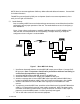
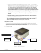
6.1.1 MDT-B Connectors
There are three connectors located on the MDT-B unit as shown in Figure 2. They are for
interfacing the RF, SDI/ASI, audio, video, power, RS-232 signals.
6.1.1.1 RF Output
The MDT-B uses a female SMA bulkhead connector for its ‘RF Output’ port.
Note: Transmitters should not be powered on without a load. Doing so could
cause the output PA to stop working.
6.1.1.2 I/O
The ‘I/O’ connector is a male, high-density DB-44. It is used to provide the interface for
external power, audio, analog video and RS-232 signals. The MDT-B has a separate
RS232 channel (labeled “Control” on the external breakout cable) for control and
monitoring the unit. GMS MDLB Configurator software program (as explained in section
6) makes use of the RS232 control lines. The RS-232 channel utilizes a 3-wire
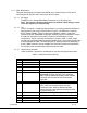
configuration. The pin out for the I/O connector is shown in Table 1. NOTE: A USB
connector and an additional RS232 channel ( labeled “DATA”) are currently provided with
the external breakout cable . The USB interface is an alternate method of interfacing to
the PC if DB-9 connectors are not available. The “Data” RS232 channel is dedicated for
low-rate data to be transmitted along with the audio and video.
6.1.1.3 SDI/ASI Input (optional)
A BNC connector is provided for Serial Digital or Asynchronous Digital data streams.
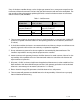
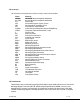
Table 2 - I/O DB-44 Connector Pin Out
Pin Signal Notes
1 RS232 Data Tx
2 RS232 Data Rx
3 RS232 GND
4 Not connected
5 SDA I^2 C bus
6 SCL I^2 C bus
7 CVBS/Y
Dual use input. 1. Composite video in; 2.
Luminance in (when used with S or Component
Video). Must be selected with GMS Control Software
or through the front panel of the in-line camera
mount box
8 GND GND for composite video
9 C/Pr
Dual use input. 1.Chroma video (when used with S-
video); 2. Pr (red component when used with
Component Video). Must be selected with GMS
Control Software or through the front panel of the in-
line camera mount box.
10 GND GND for chroma video/Pr component
11 Pb Blue component when used with Component Video.
12 GND GND for Pb component
13 GND GND
14 11-15Vdc Input power to unit