
User`s manual

100-M0056X2B 11 of 28
www.cobham.com/gms
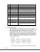
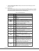
15 Not connected
16 USB power, Reset
17 USB Data -
18 USB Data +
19 USB Gnd
20-29 Not connected
30 PA_Shut_DN Provides TTL level [+3V] signal for control of external
PA
31 RS232 Control Tx
32 RS232 Control-Rx
33 RS232 GND
34-36 Not connected
37 Audio right +
38 Audio right -
39
Audio right line opt. Pin 39 is connected to pin 38 for audio right channel
input impedance of 600 ohms , balance in (mic or line
level)
40 Audio right GND
41 Audio left +
42 Audio left -
43 Audio left line opt Pin 43 is connected to pin 42 for audio left channel
input impedance of 600 ohms; balance in (mic or line
level).
44 Audio left GND
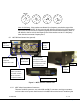
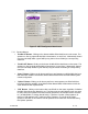
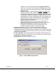
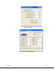
6.1.2 Frequency Select Switches
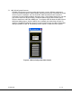
There are four external rotary switches mounted into the chassis of the MDT-B (see
Figure 2). They are used to control RF frequency selection. Frequency selection can also
be controlled through GMS control software; see section 6. The rotary switches can be
disable or enable using GMS control software; refer to section 6.3.3.2 under
Configuration/Special Setup/Others. The most significant switch (SW100) represents
1000MHz (0-9) units, the second switch (SW101) represents 100 MHz (0-9) units, the
third switch (SW102) represents 10 MHz (0-9) units and the fourth switch (SW103)
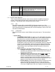
represents 1 MHz (0-9) units. Hence the highest switch selection can be 9999 MHz and
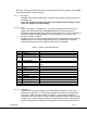
the lowest is 0000 MHz. For example with the switches in the following positions, the
frequency will read 2014 MHz:
0
9 1
6
2
3
4
5
7
8
0
9 1
6
2
3
4
5
7
8
0
9 1
6
2
3
4
5
7
8
0
9 1
6
2
3
4
5
7
8
2
0 1 4
SW100
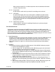
And with the switches in the following positions the frequency will read 924MHz: