
User`s manual

100-M0056X2B 17 of 28
www.cobham.com/gms
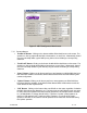
• “Store All Setup Pages” Button: Clicking on this button will store all setup pages, even if
they are not shown.
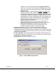
7.3.2 Field Definitions
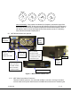
There are several different fields that can be configured by the MDT-B Configurator. The fields
located in the main screen of Figure 5 and their associated values are defined in Table 3 below.
Also noted in the table is whether the field is read, write-able or both
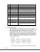
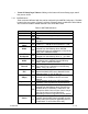
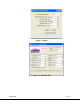
Table 4 - MDT Field Definitions
Field R/W Description
Unit Name
R/W
Allows the user to assign a unique unit name to the
MDT.
Unit Number
R/W
Allows the user to assign a unique unit number to
the MDT
RF Freq
(MHz)
R/W
RF output frequency. Desired frequency is entered
in MHz (i.e., 1.296GHz would be entered as 1296).
Modulation
Mode
R/W
Modulation mode. Desired modulation mode is
selected from the following values: COFDM
(default) Off (shuts off modulation) or I/Q CAL ON
(puts unit in calibration mode).
C-OFDM
Bandwidth
R/W
COFDM transmit bandwidth. Desired bandwidth is
selected from the following values: 6, 7 or 8 MHz.
C-OFDM
Mode
R/W
COFDM modulation type. Desired COFDM
modulation type is selected from the following
values: QPSK, 16 QAM or 64 QAM
Mod Guard
Interval
R/W
Modulation guard interval size. Desired modulation
guard interval size is selected from the following
values: 1/32, 1/16, 1/8 or ¼.
Modulation
FEC
R/W
Modulation FEC (Forward Error Correction) rate.
Desired modulation FEC rate is selected from the
following values: ½, 2/3, ¾, 5/6, 7/8.
Channel Rate
(Mbps)
R
Channel rate is displayed based on parameters
selected such as COFDM mode, FEC and Guard
Interval.
Input Mode
R/W
Choice between Analog video, SDI (serial digital
interface) or ASI (asynchronous digital interface)
Video Input
R/W
Video input format. Desired video input format is
selected from the following values: PAL, NTSC w/
Pedestal, NTSC, S-video PAL, S-video NTSC, and
Component Video. Some of these choices may or
may not be shown in the pull down box
depending on which user profile has been loaded.
Video Locked
Status
R
Analog video lock status. This read-only field
indicates that the MDT-B has line-locked onto the
analog video input signal [not applicable when the
“Input Mode” is set to either SDI or ASI]