
User`s manual

100-M0056X2B 26 of 28
www.cobham.com/gms
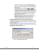
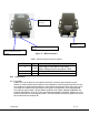
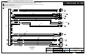
Figure 11 - BDC Connectors
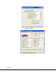
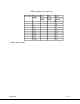
Table 5 - DB-9 Connector Pin Out for the D/C
Pin Signal Notes
1
+12Vdc
Power supply must be able to source at least
500mA. Voltage should not drop below +10Vdc.
3
GND
Power ground
2, 4-9
NC
Not Connected
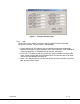
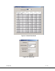
10.0 Cable Losses
10.1 Coax Cable
Cable losses must be taken into consideration if the D/C is located a great distance from the
receiver. As mentioned above long cable runs can contribute to more resistance in the lines and also
can contribute to signal attenuation because of the additional capacitance. Even when using a good
coax cable such as RG59/U the attenuation of the signal can be significant. For example, RG59/U
coax will drop approximately 2 dB per 100 feet at 50 MHz and 8 dB per 100 feet at 900 MHz. The
intermediate frequency (IF) in this system can fall between 49 MHz to 850 MHz. Cable losses in this
range for an RG59/U are shown below in table 5. An inline amplifier matching the cable losses should
be considered if losses exceed 6 dB.
DB
-
9 connector for local
power
BNC c
onnector
–
IF frequency
output
RF Input
Power Switch
for local