
User`s manual

100-M0056X2B 3 of 28
www.cobham.com/gms
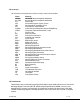
List of Tables
Table 1 – Safe Distances.......................................................................................................................................................5
Table 2 - I/O DB-44 Connector Pin Out.......................................................................................................................10
Table 3 - I/O DB-15 Connector Pin Out.......................................................................................................................13
Table 4 - MDT Field Definitions......................................................................................................................................17
Table 5 - DB-9 Connector Pin Out for the D/C.........................................................................................................26
Table 6 - RG59/U Coax Cable Losses............................................................................................................................27
List of Figures
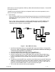
Figure 1 - Basic MDL Link Setup........................................................................................................................................ 8
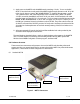
Figure 2 - MDT-B Connectors............................................................................................................................................ 9
Figure 3 - MDT-B Inline Camera Unit...........................................................................................................................12
Figure 4 - MDL_B Configurator Main Screen ............................................................................................................15
Figure 5 - MDT Configurator Main Screen.................................................................................................................16
Figure 6 - Select MPEG Encoder Profile.......................................................................................................................19
Figure 7 - Others ....................................................................................................................................................................20
Figure 7a – RF Power Off ...................................................................................................................................................20
Figure 8 - Transport Stream Setup.................................................................................................................................21
Figure 9 - Channel Rate Guide .........................................................................................................................................22
Figure 10 - FW Version .......................................................................................................................................................22
Figure 11 - BDC Connectors.............................................................................................................................................26
Appendix
Appendix A – Cable, MDT-B External Breakout for Broadcast Version .........................................................28