
User`s manual

100-M0056X2B 8 of 28
www.cobham.com/gms
NOTE: Based on customer application GMS may deliver additional cables and antennas. Contact GMS
for further information.
The MDT-B is pre-configured by GMS prior to shipment (based on customer requirements), thus is
ready to work “right out of the box”.
5.1 Initial Checkout
Prior to installing a MDT-B unit into the desired target environment, an initial checkout should be
performed to ensure proper operation of the unit. The initial checkout consists of configuring a
basic MDL-B link.
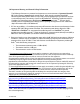
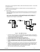
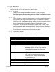
Figure 1 shows a basic configuration to establish a MDL-B wireless link (NOTE: MDR-B and D/C
units and their associated hardware are sold separately). The steps necessary to setup the
configuration shown in Figure 1 are shown below:
Figure 1 - Basic MDL Link Setup
1. Install omni-directional antennas onto the MDT-B RF output port and Down- Converter (D/C)
RF input port. Note: Transmitters should not be powered on without a load. Doing so
could cause the output PA to stop working.
2. Attach the MDT-B breakout cable (DB-44 end) to the MDT-B unit.
3. Attach a RF cable from the D/C IF output port to MDR-B IF IN #1 port.
4. Attach a composite video source to MDT-B BNC video input cable (marked CVBS/Y) that is
located on the MDT-B breakout cable. S-video and Component video input is also available.
5. Attach a video cable from one of the BNC video output ports on the MDR-B to a video
monitor.
6. To prepare to power the MDT-B unit, attach the red and black wires from the MDT-B breakout
cable to +12 V terminal and ground of power supply, respectively. NOTE: The power supply
used needs to be able to provide at least 1.2 Amp of current at a nominal +12 VDC input. To
prepare to power the MDR-B, attach +12 VDC to provided power pigtail.
7. Turn on the video source and video monitor equipment.
MDT
D/C
Video Source
Monitor
Power Supply
Power Source
MDR
MDT
-
B
MDR
-
B