
User`s manual

100-M0056X2B 9 of 28
www.cobham.com/gms
8. Apply power to the MDT-B and the MDR-B unit by attaching +12volts. To turn on the D/C,
either 1) from the front control panel of the MDR-B toggle through the menus until “R1 (or R2
in the case of diversity systems) BDC POWER DISPLAY” is displayed. Ensure power is toggle
“ON” (default mode is “ON” when shipped with down converters (D/C). [NOTE: This places
+12VDC (sourced by the MDR-B) onto the IF IN #1 port which, via the attached coax cable,
provides power up to the D/C] or 2) if using local +12 Vdc to power up the D/C then ensure the
MDR-B “R1 BDC POWER DISPLAY” is set to “OFF” and apply +12 Vdc to pin 1, GND to pin 3 of
the DB-9 pin connector located on the bottom side of the D/C. The power switch on the side
of the D/C will control the ‘ON’/’OFF’ positions for local power. See Section 8 at the end of this
document for further explanation of local and remote powering of the D/C and when to use
each one.
9. After approximately 45 seconds, the link should be established and video provided by the
source should be displayed on the monitor.
The initial checkout described above is simply to check the basic video operation of the MDT-B
unit. For further details on monitoring and controlling the MDT-B using GMS’ optional MS
Windows-based MDLB Configurator software program, see Section 6.0.
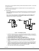
6.0 Hardware Overview
There are two basic transmitter configurations: the standard MDT-B and the inline professional
camera unit (this is an optional enclosure for mounting the standard MDT- B in professional camera
applications). The hardware for each configuration is shown below:
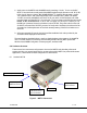
6.1 Standard MDT-B
Figure 2 - MDT-B Connectors
DB
-
44 Connector
(I/O and Power)
“RF OUT” (SMA
Frequency
Select Switches.
“SDI/ASI Input”
(BNC Connector)
SW100