
User`s manual

100-M0074X1 10 of 24
www.cobham.com/gms
If the MDT-A transmitter is used in the inline camera unit, analog audio and video
functions are not provided. The DB-15 connector and J7 (ASI input) available only.
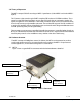
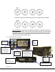
4.2.1 MDT Inline Camera Mount Connectors
There are four BNC connectors, two audio XLR, one DB-15 connector, one N type connector
and one rocker on/off power switch located on the MDT-A inline camera unit for interfacing the
RF, audio, video, power and RS-232 signals. An optional LCD control front panel is also available.
Inline camera mount is shown in Figure 3.
4.2.1.1 RF Output
The MDT in line camera enclosure uses a female N type connector (flange mount) for its
‘RF Output’ port.
Note: Transmitters should not be powered on without a load. Doing so could
cause the output PA to stop working.
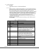
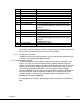
4.2.1.2 I/O
The ‘I/O’ connector is a female, DB-15. It is used to provide the interface for RS-232
signals (control and monitoring). GMS MDT Configurator software program (as explained
in section 6) makes use of the RS232 control lines, pins 2, 3 and 5 of the DB-15
connector. The RS-232 channel utilizes a 3-wire configuration. The pin out for I/O
connector is shown in Table 2. A USB connection is also provided if RS232 port is not
available.
Table 2 - I/O DB-15 Connector Pin Out
Pin Signal Notes
1 +12Vdc
2 RS232-Rx (CTRL) Relative to MDT-A (i.e., control data is input on this
pin)
3 RS232-Tx (CTRL) Relative to MDT-A (i.e., control data is output on this
pin)
4 Not connected
5 RS232-GND Common ground for both RS232 Data and Control
lines
6 I^2C_D
7 I^2C_C
8 USB Reset
+5V
9 USB Data -
10 USB Data +
11 USB GND
12 Not connected
13 RS232-Tx (DATA)
Under development/for future updates
14 RS232-Rx (DATA)
Under development
15 RS232-GND
Under development