HOW TO USE YOUR 40 CHANNEL CITIZENS BAND 2-WAY MOBILE RADIO Model 19 DX II Nothing comes close to a Cobra™ PRINTED IN THAILAND ©2002 COBRA ELECTRONICS CORPORATION 6500 WEST CORTLAND STREET CHICAGO, IL 60707 USA 480-045-P
HOW TO USE YOUR Serial No. Date of Purchase Dealer Name 40 CHANNEL Keep this manual for detailed information about your Cobra CB Radio System. SAVE YOUR SALES RECEIPT, THE CARTON AND “PACKING” FOR POSSIBLE FUTURE USE. The Cobra® line of quality products includes: CB radios ® microTALK radios Radar/Laser Detectors GPS ® Safety Alert Traffic Warning Systems Accessories HighGear™ Accessories If You Think You Need Service, please contact your local dealer.
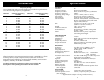
Introduction Specifications Frequency Range Your COBRA CB radio provides high-level, trouble-free performance over the following frequency assignments: Channel Channel Frequency in MHz Channel Channel Frequency in MHz 1 2 3 4 5 6 7 8 9 10 11 12 13 14 15 16 17 18 19 20 26.965 26.975 26.985 27.005 27.015 27.025 27.035 27.055 27.065 27.075 27.085 27.105 27.115 27.125 27.135 27.155 27.165 27.175 27.185 27.205 21 22 23 24 25 26 27 28 29 30 31 32 33 34 35 36 37 38 39 40 27.215 27.225 27.255 27.235 27.
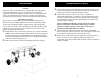
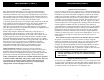
Installation Location Plan the location of the transceiver and microphone bracket before starting the installation. Select a location that is convenient for operation and does not interfere with the driver or passengers in the vehicle. In automobiles, the transceiver is usually mounted to the underneath of the dash panel, with the microphone bracket beside it.
Installation (Cont.) Installation(Cont.) CB Antenna Since the maximum allowable power output of the transmitter is limited by the FCC, the antenna is one important factor affecting transmission distance. Only a properly matched antenna system will allow maximum power transfer from the 50-ohm transmission line to the radiating element. In mobile installations (cars, trucks, boats, etc.), an antenna system that is non-directional should be used.
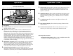
Operation Operation (Cont.) Controls and Indicators Refer to controls, indicators and connectors as illustrated below: 5. CB/PA Switch. Selects mode of operation. In the CB position, the PA function is disabled and the unit will transmit and receive on the selected channel. The PA function should not be used unless a PA speaker is connected. 6. S-RF/Power Meter. Shows relative transmitter RF output power and input signal strength when receiving.
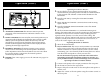
Operation (Cont.) 2 Operation (Cont.) 1. 3 Operating Procedure to Receive Be sure that the power, antenna and microphone are properly connected before proceeding further. The CB/PA switch should be in the CB mode. The Channel 9/NOR Switch should be in the NOR mode. 2. Turn the radio ON by rotating the VOLUME CONTROL clockwise. 3. Rotate SQUELCH CONTROL counterclockwise until incoming signal is heard. 1 4 4. Turn the CHANNEL SELECTOR KNOB to select the desired operating channel. B. Rear Panel 1.
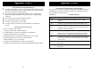
Maintenance and Adjustment Appendix Your COBRA CB transceiver is specifically designed for the environment encountered in mobile installations. The use of all solid state circuitry and its light weight result in high reliability. Should a failure occur, however, review the following, then if necessary replace parts only with identical parts. Do not substitute. Refer to the schematic diagram and parts list.
Appendix (Cont.) 1. 2. 3. 4. 5. 6. • • • • • • • • • A Few Rules That Should Be Obeyed You are not allowed to carry on a conversation with another station for more than five minutes at a time without taking a one-minute break, to give others a chance to use the channel. You are not allowed to blast others off the air by overpowering them with illegally amplified transmitter power, or illegally high antennas. You can't use CB to promote illegal activities. You are not allowed to use profanity.