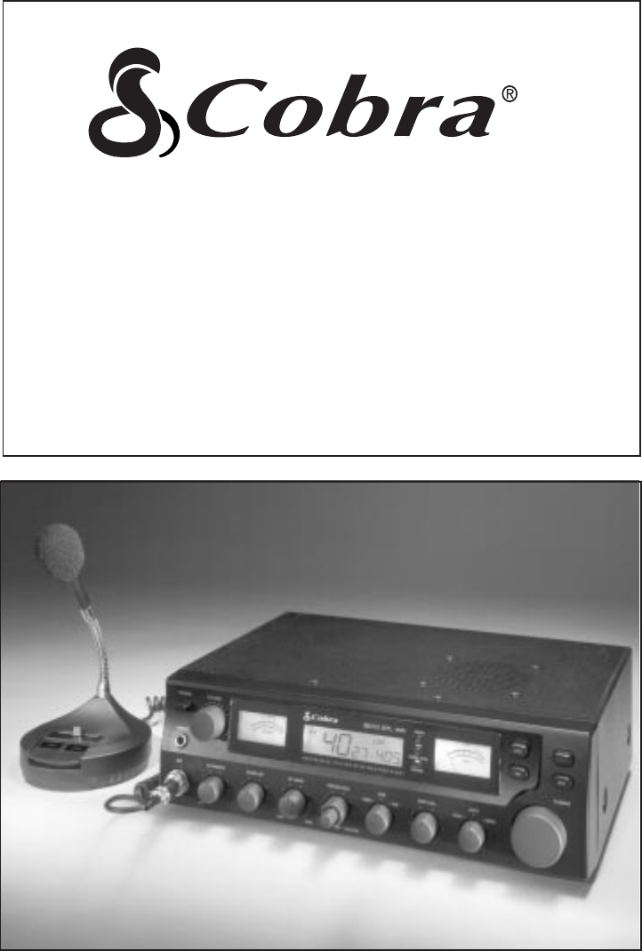
OPERATING INSTRUCTIONS FOR YOUR 40 CHANNEL SOLID STATE CITIZENS BAND SSB/AM TWO-WAY RADIO BASE STATION With Seven Weather Channels and NOAA Emergency Alert Tone Model 2010 GTL WX
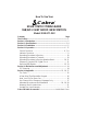
How To Use Your Cobra ® SOLID STATE CITIZENS BAND SSB/AM 2-WAY RADIO BASE STATION Model 2010 GTL WX Contents Page The CB Story .................................................................................... 1 Section I: Introduction ..................................................................... 2 Section II: Specifications ............................................................. 3, 4 Section III: Installation ....................................................................
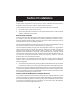
The CB Story The Citizens Band lies between the shortwave broadcast and 10-meter Amateur radio bands, and was established by law in 1949. The Class D two-way communications service was opened in 1959. (CB also includes a Class A citizens band and Class C remote control frequencies.) FCC regulations permit only “transmissions” (one party to another) rather than “broadcasts” (to a wide audience). Thus, advertising is not allowed on CB Channels because that is “broadcasting.
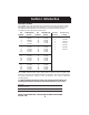
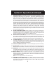
Section I Introduction FREQUENCY RANGE The COBRA 2010 GTL WX transceiver represents one of the most advanced AM base station radios used as a Class D station in the Citizens Radio Service. This unit features advanced Phase Lock Loop (PLL) circuitry providing complete coverage of all 40 channels as shown below. CB Channel Channel Freq. CB Channel Freq. in MHz Channel in MHz 1 2 3 4 5 26.965 26.975 26.985 27.005 27.015 21 22 23 24 25 27.215 27.225 27.255 27.235 27.245 6 7 8 9 10 27.025 27.035 27.
Section II Specifications GENERAL Channels Frequency Range Frequency Control Frequency Tolerance Operating Temperature Range Microphone Power Source Power Consumption Current Drain (13.8V DC) Size Weight Antenna Conductor Semiconductors Meter 1 Meter 2 40. 26.965 to 27.405 MHz. Phase Lock Loop (PLL) synthesizer. ±130 Hz Typical. -30° C to + 50° C. Plug-in type; 600Ω dynamic. 120V AC nominal. 13.8V DC nominal. (Positive or negative ground). Transmit: AM full mod., 65 watts. SSB 70 watts.
Section II Specifications (Cont.) RECEIVER Sensitivity Selectivity Image Rejection IF Frequency Adjacent-Channel Rejection AM and SSB RF Gain Control Automatic Gain Control (AGC) Squelch ANL Noise Blanker Voice Lock Range Audio Output Power Frequency Response Built-in Speaker External Speaker (Not Supplied) SSB: 0.25 µV for 10dB (S+N)/N at greater than 1/2-watt of audio output. AM: 0.5 µV for 10 dB (S+N)/ at greater than 1/2-watt of audio output. AM: 6dB @ 3 KHz, 50 dB @ 9 KHz. SSB: 6 dB @ 1.
Section III Installation LOCATION Prior to beginning operation of the transceiver, a basic installation must be prepared. Installation of the transceiver itself is a rather simple procedure. In selecting the location for the unit, two basic factors must be considered: 1. Access to a 120V, 60 Hz power source. 2. The location must be convenient for running the antenna lead-in cable if outside antenna installation is proposed.
Section IV Operation CONTROLS AND INDICATORS There are eighteen controls, 2 meters, 1 LCD and 1 jack on the front panel of your 2010 GTL WX. 3 12 11 17 POWER 1 VOLUME 5 6 9 10 11 7 8 12 13 14 15 4 3 RF PWR 2 3 16 17 18 19 PHONE 0 20 16 1 3 SIGNAL 9 RX TX ANT +30 AM / SSB MIC DYNAMIKE 2010 GTL WX 4 5 SQUELCH RF GAIN USB LSB AM HOUR MOD MIN 1.5 FREQ.
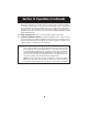
Section IV Operation (Continued) 6. SWR CAL CONTROL . In order for you to achieve maximum radiated power and the longest range, it is important that your antenna be in good condition, properly adjusted and matched to your transceiver. The Built-in SWR (standing wave ratio) meter lets you easily measure your antenna condition. To operate this function, connect your antenna to the transceiver antenna output connector.
Section IV Operation (Continued) 15. PRESS-TO-TALK MICROPHONE. The receiver and transmitter are controlled by the press-to-talk switch on the microphone. Press the switch and the transmitter is activated; release switch to receive. When transmitting, hold the microphone two inches from the mouth and speak clearly in a normal "voice." The radio is supplied with a low-impedance 500-ohm dynamic desktop microphone. For installation instructions on other microphones, see "ALTERNATE MICROPHONES AND INSTALLATION.
Section IV Operation (Continued) POWER 6 5 3 7 1 2 100% ANL VOLUME 5 6 9 10 11 7 8 12 13 14 15 4 3 RF PWR 2 3 16 17 18 19 PHONE 0 20 1 3 SIGNAL DYNAMIKE 2010 GTL WX 4 5 9 +30 RX TX ANT AM / SSB MIC 4 SQUELCH RF GAIN USB LSB AM HOUR MOD MIN 2 1.5 FREQ. CTR BASE STA TION WITH WEATHER ALERT CLOCK VOICELOCK LSB USB AM 3 0 CH 9 CAL SWR NB WX TUNING SWR CAL SWR CAL MOD MIN MAX COARSE 8 INDICATOR FUNCTIONS 1. MODULATION METER.
Section IV Operation (Continued) OPERATING PROCEDURE TO RECEIVE 1. Place the WX/CB Switch in the CB position. 2. Turn the set ON by pressing the POWER Switch. 3. Adjust the VOLUME for a comfortable listening level. 4. Set the Channel selector switch to the desired channel. 5. Set RF GAIN fully clockwise. 6. Set the Mode Selector to desired mode for LSB, AM or USB. 7. Adjust the VOICE LOCK control to clarify the SSB signals or to optimize AM signals. 8. Listen to the background noise from the speaker.
Section IV Operation (Continued) OPERATING PROCEDURE TO RECEIVE WEATHER BAND continued 3. If threatening weather is nearby, the National Weather Service may broadcast a 10 second alert tone. This tone will be heard through the CB, even if the WX/CB Switch is in the CB mode or the unit is turned off (see NOTE below). This enables you to monitor CB frequencies and still be warned by the National Weather Service Emergency Alert. When you hear the alert, place the WX/CB Switch in the WX position.
Section IV Operation (Continued) RECEIVING SSB SIGNALS There are three types of signals presently used for communications in the Citizens Band: AM, USB, and LSB. When the MODE switch on your unit is placed in the AM position, only standard double-sideband, full carrier signals will be detected. An SSB signal may be recognized while in the AM mode by its characteristic “Donald Duck” sound and the inability of the AM detector to produce an intelligible output.
Section IV Operation (Continued) RECEIVING SSB SIGNALS continued Once the desired SSB mode has been selected, frequency adjustment may be necessary in order to make the incoming signal intelligible, the VOICE LOCK control allows the operator to vary frequency above and below the exact-center frequency of the received signal. If the sound of the incoming signal is high or low pitched, adjust the operation of the VOICE LOCK. Consider it as performing the same function as a phonograph speed control.
Section V Maintenance and Adjustment The COBRA 2010 GTL WX transceiver is specifically designed for the environment encountered in base station installations. The use of all solid state circuitry and its light weight result in high reliability. Should a failure occur, however, replace parts only with identical parts. Do not substitute. Refer to the schematic diagram and parts list.
Section VI Appendix Citizens Band operators have largely adopted the “10-code” for standard questions and answers. Its use permits faster communications and better understanding in noisy areas. The following table lists some of the more common codes and their meanings.
Section VI Appendix (Continued) A FEW RULES THAT SHOULD BE OBEYED 1. You are not allowed to carry on a conversation with another station for more than five minutes at a time without taking a one-minute break, to give others a chance to use the channel. 2. You are not allowed to blast others off the air by over-powering them with illegally amplified transmitter power, or illegally high antennas. 3. You can’t use the CB to promote illegal activities. 4. You are not allowed to use profanity. 5.
Section VI Appendix (Continued) USE CHANNEL 9 FOR EMERGENCY MESSAGES ONLY FCC gives the following examples of permitted and prohibited types of communications for use on Channel 9. These are guidelines and are not intended to be allinclusive. Permitted Example Message Yes ”A tornado sighted six miles north of town.” No ”This is observation post number 10. No tornado sighted.” Yes ”I am out of gas on Interstate 95.” No ”I am out of gas in my driveway.
Section VI IV Appendix Operation(Continued) (Continued) ALTERNATE MICROPHONES AND INSTALLATION For best results, the user should select a low-impedance dynamic type microphone or a transistorized microphone. Transistorized type microphones have a low output impedance characteristic. The microphones must be provided with a five-lead cable. The audio conductor and its shielded lead comprise two of the leads. The third lead is for receive control, the forth is for grounding and fifth is for transmit control.
Section VI Appendix (Continued) Fig. 4. Microphone plug pin numbers viewed from rear of pin receptacle. Be sure that the housing and the knurled ring of Fig. 3 are pushed back onto the microphone cable before starting to solder. If the washer is not captive to the pin receptacle body, make sure that it is placed on the threaded portion of the pin receptacle body before soldering.
Section VI Appendix (Continued) Fig. 2. Microphone Cable Preparation To wire the microphone cable to the plug provided, proceed as follows. Fig. 3. Microphone plug wiring. 1. Remove the retaining screw. 2. Unscrew the housing from the pin receptacle body. 3. Loosen the two cable clamp retainer screws. 4. Feed the microphone cable through the housing, knurled ring and washer as shown Fig. 3B. 5. The wires must now be soldered to the pins as indicated in the above wiring tables.
If You Need Service If You Think You Need Service, Call 773-889-3087 You may be asked to send your unit to the Cobra factory. It will be necessary to furnish the following, in order to have the product serviced and returned. 1. For Warranty Repair, include some form of proof-of-purchase, such as a mechanical reproduction or carbon or a sales receipt. If you send the original receipt it cannot be returned. 2. Send the entire product. Must include CB unit and microphone. 3.
WARRANTY Limited Two Year Warranty COBRA ELECTRONICS CORPORATION warrants that its COBRA citizens band (CB) radio, and the component parts thereof, will be free of defects in workmanship and materials for period of two (2) year from the date of first consumer purchase. This warranty may be enforced by the first consumer purchaser, provided that the product is utilized within the U.S.A.
FOLD THIS FLAP OVER BOTTOM AND TAPE IT DOWN AND SIDES TO CLOSE COBRA CB RADIO ACCESSORIES Cost Ea. X Qty. = Amount AT-55 Cellular-Style Glass-Mount Antenna for 2010 GTL WX AT-55 $24.95 CA-72 BASE STATION MICROPHONE with 5-pin connector for 2010 GTL WX CA-72 $53.95 CA-78, MOBILE POWER MICROPHONE Amplified Power Microphone with 5-pin connector for 2010 GTL WX CA-78 $39.95 ATW-400 DUAL BAND ANTENNA, Magnetic mount with 15' RG58U Cable and PL-259 connector ATW-400 $39.
FOLD HERE TO MAKE SELF MAILER PLACE STAMP HERE Cobra ® Cobra Electronics Corporation 6500 W. Cortland Street Chicago, IL 60707 PRINTED IN MALAYSIA ©COBRA ELECTRONICS CORP.