SERVICE CRANE Code Rev Edition MD.0.141 0 07/09 Mod.
OPTIONALS SUPPLIED ALONG WITH THE CRANE Description YES NO Oil tank Outrigger beam - (mechanical jack) Outrigger beam - (hydraulic jack) The table has to be filled carefully with the above option when purchased PRELIMINARY INFORMATION Operator’s and maintenance manual of MAXILIFT COBRA 4400 SERVICE CRANE Manual code: MD.0.141 This manual is valid starting from serial no: .......... Manufacturer: NEXT HYDRAULICS S.r.l.
INDEX 1 FOREWORD .................................................................................................. PAGE 1 1.1 1.2 1.3 Summary ........................................................................................................................................................ “ Remarks ......................................................................................................................................................... “ Manual revision ..............................
6.5 6.5.1 6.5.2 6.6 6.6.1 6.6.2 6.6.3 6.6.4 6.6.5 6.6.6 6.6.7 Remote control use ................................................................................................................................ Page Use of the mono-function proportional remote control .................................................................................. “ Use of the dual-mode proportional remote control .......................................................................................
1 FOREWORD 1.1 SUMMARY This manual is divided into chapters to make its consultation easier. Chapter 1: Chapter 2: Chapter 3: Chapter 4: Chapter 5: Chapter 6: Chapter 7: Chapter 8: Chapter 9: Includes summary and a short introduction. Explains how to consult the manual. Crane identification data. Limits of crane operation and usage. Safety rules. Description of the crane, safety devices and controls. Description of operation and usage tips. Crane starting up and storage.
NOTE The table on the back of the front page has to be filled at customer’s care. It contains all the necessary data required when calling our Technical Service. A copy of this manual is supplied along with every crane. Data, descriptions and pictures of this manual are not binding. The Manufacturer reserves the right to change at any time all the items, components and parts deemed to be necessary for product improvement or commercial or production needs.
3 CRANE IDENTIFICATION 3.1 VERSIONS AND OPTIONS AVAILABLE The service instructions written on this manual are referred to the CRANE MAXILIFT COBRA 4400. This model is supplied in 6 versions.
4 CRANE USAGE AND LIMITS OF APPLICATIONS 4.1 CRANE CLASSIFICATION AND PROPER USAGE The machine is an hydraulic truck crane for hook service. It can also be used for the same purpose from a static mounting. The lifting capacity is 2.2 ton-meter (16,000 ft. lbs.), making it especially suitable for installation on light truck. The crane is classified in class H2-B3 according to DIN 15018 standards, and must be used accordingly, that is: trucks loading/unloading, hook service. 4.
• • • • • • normal depth perception and field of vision (peripheral); ability to distinguish colors if color recognition or differentiation is, required for safe operation; adequate hearing, with or without a hearing aid; sufficient strength, endurance, agility and coordination to meet equipment operation demands; emotionally stable; not subject to seizures, loss of physical control, dizziness or have physical limitations which could impair the ability to safety operate the crane.
5 SAFETY RULES 5.1 RULES CONCERNING PEOPLE • Always wear the prescribed personal safety devices • Always wear approved accident-prevention clothing such as: protective helmets, anti-slip shoes, protec tive gloves, antinoise headphones, protective glasses, reflective jackets with breathing apparatus. Con sult your employer regarding current safety regulations and accident-prevention equipment.
5.3 RULES FOR THE CORRECT POSITIONING OF THE CRANE 5.3.1Choice of crane operating place pressure on the ground • Carefully choose the place where lowering and put into action the stabilizers of the crane outriggers. The most important thing is the capacity of the ground to bear the pressure produced by the outriggers. • Make sure that the outriggers working area is free from underground piping, tunnels, holes.
• for brought-back or crumbling terrain safety distance (a) must be double of the slopes’ depth that is: a=2•b • for compacted, not crumbling terrain safety distance (a) must be equal to the slopes’ depth, that is: a=1•b Distance to be measured from point © Max. reaction on the ground varies according to the vehicle where the crane is installed. IMPORTANT The installer must calculate this max. reaction on the ground and applied the value on the outrigger jacks. Pict. 3 5.3.
Grounding is especially required when: • working close to electric power lines; • working nearby powerful broadcasting plants such as radio, T.V.
! DANGER electrocution hazard Always connect in a perfect way the load and the ground Before touching the load with your hands, always ground the load by touching it with the insulated rod. ! DANGER electrocution hazard Always hold the rod by its insulated handle. 5.3.5 Influence of the wind on the crane operation A strong wind can overload the crane, so during operations keep under control the wind speed. When working with full load, the maximum admittable wind speed is 45 km/h (28 mile/h).
5.5 GENERAL RULES ON WINCH OPERATIONS 5.5.1 Winch system operation The Winch is mounted at the rear of the first section boom.It has capacities totally indipendent of the rest of the crane and can normally pull more than the crane itself can withstand.Therefore,care must be taken to insure that the load being lifted is within boom rating.
5.6 WIRE ROPE 5.6.1General Wire rope can be the weak link in crane safety. It is subjected to heavy loads, abrasion, kinking, extreme weather conditions, chemical attack and other forces which can reduce its reliability. The inspection and care of wire rope is essential in the effort to provide for safe working conditions. 5.6.2Wire rope precautions 1 - Avoid the formation of kinks. Kinks will cause severe weakness in the rope. No corrections are availa ble for kinked rope.
6 DESCRIPTION OF THE CRANE 6.
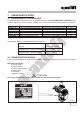
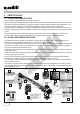
6.2 Model 4400 E 12V/24V Item 1 2 3 4 5 6 7 8 9 10 11 12 13 14 15 16 17 Description Slewing system Slewing motor Column Main boom Boom hoist cylinder First hydraulic boom section Second mechanical boom section Telescope cylinder Hydraulic unit Electronic Power unit Cable or radio remote control box Winch Travelling block Electro-hydraulic power pack Outrigger beam (mechanical jack) OPTIONAL Outrigger beam (hydraulic jack) OPTIONAL 8 7 6 14 16 15 13 4 10 11 17 5 3 1 2 Pict.
6.3 SAFETY DEVICES 6.3.1Safety devices installed All the safety devices,installed on MAXILIFT COBRA 4400 crane, are listed and described in the following pages. description of safety functions The crane is fitted with 4 standard electro-hydraulic safety limitations: 1) The load limiting device, which intervent each time the load mentioned on loading diagram is excee ded and locks the crane, stopping all mouvements, except re-entry of boom extension and lowering the load. 2) 0° working placing of the boom.
6.3.3Relief valve The main relief valve is on the control valve and limits the maximum working pressure. 6.3.4Pilot operated holding valves These valves are installed on every cylinder and will stop and lock every motion of the cylinder should any pressure loss occur.
6.4 MICROPROCESSOR REMOTE CONTROL SYSTEM COBRA cranes are equipped with an advanced microprocessor remote control system that correctly manages the crane operations as well as its safety devices and provides indications to help the operator performing rapid troubleshooting or adjustments when necessary. 6.4.
6.4.3 THE RADIO RECEIVER UNIT (Pict.10) The radio control version unit (3) is externally equal to the remote control version, internally, it includes the electronic system that manages machine logic and radio module and works as a receiver; a safety system prevents other transmitters from entering the system since it only recognizes its matched keyboard (transmitter) through the RFID code (radio frequency identifier).
6.4.5 THE KEYBOARD – RADIO TRANSMITTER (Pict.10) The operator interface is identical to the 2 5 abovementioned one. 4 The differences are: The absence of the integral cable, replaced by a connector at the base of the handgrip to connect the battery supply serial cable (1). This 2 m. cable is 3 included in the standard supply and it charges the keyboard batteries; it can also be used to control the crane through cable system.
6.4.5.1 RADIO SYSTEM PROTECTION DEVICES The radio control system is provided with some protection systems that are automatically started in case of: - radio interference on the crane working area that influences the radio control frequency range - transmitter capacity field exceeded (keyboard) On these cases the system locks all the functions.
6.4.7 PROPORTIONAL DUAL-MODE REGULATION HYDRAULIC UNIT (Pict.12) The unit is consisting of two separate aluminium blocks. The upper section includes the proportional adjusting valve (VR), the manual bypass control valve (OM) of the proportional regulator, the main relief valve (VM), the winch operating solenoid valves (EV4A – EV4B), the dump valve (EV9) and the solenoid valves (EV3 – EV4) required to operate the winch and another function at the same time.
6.5 REMOTE CONTROL USE After the preliminary operations concerning: - PTO engaging - extension and lowering of stabilizer legs and their levelling - control system supply by switching on the proper switch inside the cabin - power supply by turning the battery-disconnecting lever in case of electro-hydraulic crane you can go on working with the remote control. 6.5.1 USE OF THE MONO-FUNCTION PROPORTIONAL REMOTE CONTROL First, release the emergency button (E).
6.6 SIGNALS AND DIAGNOSTIC 6.6.1 KEYBOARD DIAGNOSTIC SIGNALS The following signal devices are found on the radio keyboard: - a beeper - a green led Beeper signals: Radio connection keyboard: - a brief signal (beep) indicates that the keyboard is powered (through the emergency button) - a long signal (beep) indicates that the RFID code (radio frequency identifier, exclusively used by authorized workshops) self-learning procedure has been activated.
6.6.2 DISPLAY MESSAGES As previously explained, the electronic control unit is fitted with a 3 digits display showing messages which help the operator understanding if everything is working properly, the operating state and the functioning of its electrical components. The operator, when led by an expert or following basic operations, can actually read on such display different messages helping him locating possible electrical anomalies on the system.
The following table shows all the displayed alarm codes.
6.6.4 MICRO-SWITCHES AND PRESSURE SWITCH DISPLAY MENU This menu is accessed from the Normal Display Menu through the following procedure: push the proportional button to its maximum level, then operate the 1A and 3B movements simultaneously for at least 5 seconds (the maneuver can be performed in radio mode or through serial cable). . In this menu the state of FA, FB, FV, PM micro-switches are displayed cyclically, with a 2.
6.6.6 REMOTE CONTROL KEYBOARD DISPLAY MENU This menu is accessed from the Normal Display Menu through the following procedure: push the proportional button to its maximum level, then operate the 1A and 2B movements simultaneously for at least 5 seconds (the maneuver can be performed in radio mode or through serial cable). In this menu, when no operation is active, the indication “_ _ _” is displayed.
6.6.7 WORK PRESSURE DISPLAY MENU This menu is only available on the momentum limiter system with analog pressure transducer and it displays the real time oil hydraulic pressure (in bar). This menu can be accessed from the normal display menu through the following procedure: Fully press the proportional button and simultaneously start maneuver 1A and the STOP selector for 5 seconds (the maneuver can be performed in radio mode or through serial cable).
7 OPERATING INSTRUCTIONS 7.1 GENERAL ATTENTIONS The crane must be used exclusively by qualified and skilled operators. They must know location and function of every control, instruments, indicators, lights, plate and sticker. ! DANGER Before starting operations make sure that nobody is in the working area of the crane. • The crane must work only on flat ground. • Make sure that the truck is well braked and, if necessary, apply blocks to the tires.
• Check every month the state and correct functioning of all the parts subject to wear: pins, valves, hoses, sliding pads and bushings, etc. If necessary replace with genuine spare parts. • It is absolutely forbidden to alterate the hydraulic circuit and open the safety seals. Failure to comply will cause automatically the voiding of any warranty on the product. Valves adjustments or setting must be done only by authorized installer workshops.
ATTENTION The outrigger beam is in its working position when the yellow band existing on the beam can be entirely seen. • Lower to the ground the bearing pads of the outriggers jacks, one at a time, acting as follows: Hydraulic jack (Fig. 16) Open the shut-off valve (1) to allow the lowering to ground of the cylinder’s pad and rod (2). The valve is open when its lever is on position “A”. Operate the corresponding lever of the control valve until the pad reaches the ground.
7.3 OPENING THE CRANE • Starting from the crane in rest position, operate the switch of „boom hoist up“ on remote control. When the boom is roughly horizontal or in any case, higher than vehicle sides or other existing obstacles. • Then operate the switch “crane swing”, to direct the boom in the desired direction. • Then operate the switch “boom section extend” until the hook has reached the required position. 7.
• Hitting the rope where the load is suspended, overload is generated. • Side pull, dragging the load on the ground. All these operations originate strong overloading forces on the crane. • The outriggers are badly positioned or the ground is not firm: in both cases the truck tilts and could tip over. • Working with strong wind or wind gusts • The manual boom sections are not correctly installed. • The load is not correctly slinged.
8 PUTTING THE CRANE INTO SERVICE 8.1 TEN RULES FOR THE PERFECT CRANE OPERATOR Always comply with the following ten basic rules: 1 - When approaching the crane for the first time, become on familiar terms with it, executing all the manoeuvres the crane can perform during working. Carefully read all the prescriptions of this manual and execute step by step the activities hereby described to be sure of the correct under standing.
ATTENTION Never wash the crane with chemical products or high pressure water jets, as they can cause the detaching of the stickers water entering inside the electrical components and the slewing case. 8.4.2 Long shutdowns Same precautions as above and, moreover: • • • • apply protective oil on the entire crane surface cover the crane using a plastic curtain against rain etc. store in a dry place, under roof disconnect the connections to the truck battery.
9 MAINTENANCE 9.1 WARNINGS • Do not wear rings, wristwatches, jewelry, loose-fitting or hanging clothing such as ties, torn garments, ordinary shoes, unbut toned jackets or un-zipped overalls, which could get caught up in the moving parts of the crane. Instead, always wear approved accident-prevention clothing such as protective helmets, anti-slip shoes, anti-noise headphones, protective glasses, and reflective jackets with bre athing apparatus.
! DANGER of fire or scald It is forbidden to use naked flame as lighting device when carrying out checks or looking for leaks in the machine. • Do not lubricate, repair or carry out settings on the crane when it is working, unless this is expressly required in the instructions of the Operator’s/Maintenance manual.
9.3.2 Monthly checking • • • • • • • • • • • • Check the setting of the pressures in the hydraulic system, and integrity of the seals. Check the absence of oil leaks. Check integrity and tightening of crane tie rods and bolts. Check integrity and tightening of hoses, piping and their fittings. Check fastenings and safety devices. Check readability of symbols on the remote control. Check integrity of hooks, ropes, chain and all the other lifting ancillary equipment.
9.4 CRANE SERVICING 9.4.1 Oil level checking The oil level must be checked daily, with the crane in rest position and the truck on flat ground If necessary top up with hydraulic oil. The level is checked by mean of the dipstick. (1) 9.4.2 Oil change The oil deteriorates during daily usage. The oil change every year is necessary to avoid damages to the hydraulic system. Take a container with a capacity of 40 liters (10 gal.) and having suitable dimensions to be positioned under the oil drain plug.
9.4.4 Wormgear assembly control (Pict. 21) It is important to check that the worm gear reducer has a correct axial backlash. This can be made, with the crane at standstill, the boom in horizontal position. Pushing the boom aside on the left and on the right by hand, you can notice if the axial backlash between the wormshaft (6) and the wormgear (8) is too great. In this case it has to be reduced, tighten the nut (7) accordingly.
9.5 Greases and oils reference table BRAND TOTAL MOBIL ESSO AGIP IP BP GREASE MULTIS MOBILGREASE BEACON GR MU ATHESIA ENEGREASE EP2 MP EP2 EP2 EP2 LR MP GREASE MULTIS LR MP MOBILGREASE MP BEACOM EP2 GR MU EP2 ATHESIA EP2 ENERGREASE EP2 HYDRAULIC OIL AZOLLA ZS 46• DTE 25 NUTO H 46• OSO 46• HYDRUS 46 HENERGOL HL 80 H68* 68 * ZS 48* GREASE WINN’S (GS-80) • for temperate and cold climate * for hot climate Pict.
9.6 WIRE ROPE 9.6.1 WIRE ROPE INSPECTION Each day and before use, inspect the wire rope for the following conditions: 1 2 3 4 5 - Kinking (Sharp bends) Crushing Unstranding Birdcaging Core protrusion 6 7 8 9 10 ! - Rope diameter loss Rope strand uneveness General corrosion Broken strands Cut strands DANGER Do Not open the rope for inspection. Inspect the rope daily or before use each day and also inspect the rope eye for abrasion, corrosion and broken wires.
9.6.3 WIRE ROPE LUBRICATION Wire rope is lubricated during manufacturing so the strands, and individual wires in strands, may move and adjust as the rope moves and bends. A wire rope cannot be lubrificated sifficiently during manufacture to last its entire life. Therefore, new lubricant must be added periodically throughout the life of a rope to replace factory lubricant which is used or lost. The surface of some ropes may become covered with dirt, rock dust, or other material during their operation.
9.7 POSSIBLE FAULTS AND RELEVANT REMEDIES Fault Cause Remedy Vibrations in hydraulic cylinder and jerkin- The temperature of the hydraulic oil is Perform manoeuvres without loads for gs at the first manoeuvres. too low. some minutes to warm the oil up. Vibrations with every functions when the Lacking of oil in the tank. Air in the hydrau- Add hydraulic oil to the tank. oil is hot. lic system. Operate the control lever carrying the cylinders to stroke end for some times in both directions.
Fault Cause Remedy One of the function does not work. Defective switch Replace the switch Burned solenoid. Replace the solenoid. Locked valve cartridge Disassemble and clean the valve cartridge Damaged electric connection.
10 TECHNICAL DATA - WINCH SPECIFICATIONS SERIES 4400 STANDARD EQUIPMENT - High speed winch with planetary gears reducer - Remote control with connection and 10 m. - 33’ ft.
TECHNICAL DATA 4400 Crane rating Standard outreach Slewing angle Boom elevation Lifting height from base of crane Remote control Pump capacity hydraul. “H” (pto) Working pressure Crane weight ft.lbs ft. GPM psi lbs 16.000 15’ 9” 400° (-5° +80°) 15’ 9” Proportional 2.7 2830 700 lbs ft./min ft./min inch. ft. lbs 2.200 40 23- 36 5/16” 98 minimum 11.365 ft.
11 WIRING AND HYDRAULIC DIAGRAMS 11.1 ELECTRICAL DIAGRAMS Pict.
11.1 DESCRIPTION SW1 SW2 SW3 SW4 SW5 SW6 L1 ES 1 2 V3 V4 EV1A EV1B EV2A EV2B EV3A EV3B EV4A EV4B FA FV FB PM PT VR SC EV9 -Crane rotation selector -Boom movement selector -Extension selector -Winch selector -Engine start/stop selector -Optinal function selector (opt) -Green led -Emergency push button -Circuit board -Proportional trigger button -Winch electro-valve solenoid -Winch electro-valve solenoid -Clockw. rotation electrov. solenoid -Counter clockw. rotation electrov.
11.2 HYDRAULIC DIAGRAMS 11.2.1 Hydraulic diagram mono-function proportional 1 2 3 4 5 6 7 8 9 10 11 12 13 14 Pump Electrohydraulic unit Rotation motor Lifting cylinder Overcenter valve Pressure switch Extension cylinder Overcenter valve Oil filter Oil tank Winch motor Pict.
11.2.2 Hydraulic diagram dual-mode proportional 1 2 3 4 5 6 7 8 9 10 11 12 13 14 Pump Electrohydraulic unit Rotation motor Lifting cylinder Overcenter valve Pressure switch Extension cylinder Overcenter valve Oil filter Oil tank Winch motor Pict.
NOTES Name of the installer (person) Name of the authorized installer workshop NEXT HYDRAULICS S.r.l. Address City Province Tel number. State Date Via Mediterraneo , 6 Boretto 42022 (RE) - ITALY Tel. 0522/963008 - Fax 0522/963039 e-mail: nexthydraulics@tin.it COPYRIGHT BY NEXT HYDRAULICS S.r.l. Layout and pubblication by “ Studio Tecnico Pinotti” Reproduction and distribution are forbidden according to law without written permission in writing from Next Hydraulics S.r.l.
NEXT HYDRAULICS s.r.l. Via Mediterraneo, 6 42022 Boretto (Reggio E.) -Italy Tel. 0522/963008 - Fax 0522/963039 e-mail: nexthydraulics@tin.