600mm Gas Barbeque Model CB6 INSTALLATION AND OPERATION MANUAL For use in GB, IE & DK 230582-7
MANUFACTURED BY Moffat Limited Christchurch New Zealand INTERNATIONAL CONTACTS AUSTRALIA Moffat Pty Limited E.Mail: Main Office: Service: Spares: Customer Service: vsales@moffat.com.au (tel): +61 (03) 9518 3888 (fax): +61 (03 9518 3833 (tel): 1800 622 216 (tel): 1800 337 963 (tel): 1800 335 315 (fax): 1800 350 281 CANADA Serve Canada Web: E.Mail: Sales: Service: www.servecanada.com info@servecanada.com (tel): 800 551 8795 (Toll Free) (tel): 800 263 1455 (Toll Free) NEW ZEALAND Moffat Limited Web: E.
Contents CB6 Gas Barbeque Part 1 Introduction ..................................................................................... 2 Part 2 Specifications .................................................................................. 3 Part 3 Installation ........................................................................................ 4 Part 4 Operation ......................................................................................... 6 Part 5 Cleaning and Maintenance .........
Part 1 Introduction We are confident that you will be delighted with your Cobra Series Barbeque, and it will become a most valued appliance in your commercial kitchen. To ensure you receive the utmost benefit from your new Cobra Appliance, there are two important things you can do. Firstly: Please read this instruction book carefully and follow the directions given. The time taken will be well spent.
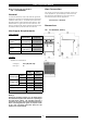
Part 2 Specifications Model Covered in this Specification - Gas Connection CB6 GAS BARBEQUE. Gas supply connection point is located at the rear of the appliance, approximately 215mm from the left hand side and 535mm from the floor and is entered from beneath the appliance. General A commercial heavy duty, fully modular, gas fired barbeque created for modular kitchens supplied in a 600mm wide option.
Part 3 Installation Installation Requirements Location NOTE: It is most important that this appliance is installed correctly and that operation is correct before use. Installation shall comply with local, gas, health and safety requirements. 1. 2. Installation must allow for a sufficient flow of fresh air for the combustion air supply. This appliance must be installed in a suitably ventilated room to prevent dangerous build up of combustion products.
Part 3 Installation NOTE: A Manual Isolation Valve must be fitted to the individual appliance supply line. Gas Connection NOTE: ALL GAS FITTING MUST ONLY BE CARRIED OUT BY A QUALIFIED SERVICE PERSON. 5. Correctly locate the appliance into its final operating position and using a spirit level, adjust the legs so that the unit is level and at the correct height. 6. Connect the gas supply to the appliance. 7. Verify the operating pressure is as shown in the 'Specifications Section'. 8.
Part 4 Operation Lighting the Pilot Burner Operation Guide NOTE: All Barbeque models incorporate the push button piezo ignition system for each individual pilot burner. C AUTI ON : This appliance is for professional use and is only to be used by qualified people. Only qualified service persons should be used to carry out installation, servicing or gas conversion operations. Components having adjustments protected (e.g.
Part 5 Cleaning and Maintenance C AUTI ON : Weekly Cleaning NOTE: Always turn off the gas and electrical supply at the mains supply before cleaning. This appliance is not water proof. Do not use water jet spray to clean interior or exterior of this appliance. If the Barbeque usage is very high, we recommend that the weekly cleaning procedure is carried out on a more frequent basis. Ensure that protective gloves are worn during the cleaning process.
Part 5 Cleaning and Maintenance Periodic Maintenance c. To remove any discolouration, use an approved stainless steel cleaner or stainless steel wool. Always rub in the direction of the grain. d. Remove the grease tray and clean with a mild anti bacterial detergent and hot water solution using a soft bristled brush. e. Dry the grease tray thoroughly with a dry cloth. f. Dry all components thoroughly with a dry cloth and polish with a soft dry cloth.
Part 6 Gas Conversion 6. Unscrew the main burner injectors from the barbeque using a 13mm / 1/2" A/F spanner. Gas Conversion Procedure C AUTI ON : Main Burner Injector Ensure that the Unit is isolated from the gas supply before commencing servicing. NOTE: These conversions should only be carried out by qualified persons. All connections must be checked for leaks before re-commissioning the appliance.
Part 6 Gas Conversion Low Fire Adjustment (All Models) 3. Determine the correct injector size for the corresponding gas from the table shown in the 'Gas Specifications' section on page 3. Thermocouple 1. To set the burner low fire adjustment, the low fire adjustment screw on the gas control valve should be screwed fully in, then un-screwed by the measurement shown in the 'Gas Specifications' table.
Part 6 Gas Conversion Gas Type Labels On completion of the gas conversion, replace gas type labels located at:- The rear of the unit, above the gas connection. - Beside the rating plate. Commissioning Before leaving the converted installation; 1. Check all gas connections for leakages using soapy water or other gas detecting equipment. WARNING: DO NOT USE A NAKED FLAME TO CHECK FOR GAS LEAKAGES. 2.
Part 6 Gas Conversion Gas Specifications - Australia / New Zealand Only: Natural Gas LP Gas (Propane) Main Burner Injectors 2.70 mm 1.65 mm Pilot Burner Injectors 0.45 0.30 Low Fire Adjustment 11/4 turns out (ccw) ½ turn out (ccw) 1.13 - 3.40 kPa 2.75 - 4.50 kPa Operating Pressure 0.95 kPa (*) 2.6 kPa (*) Main Burner Aeration Shutter Fully Open Fully Open Supply Pressure Gas Regulator Cap Screw - CE Only: Appliance Classification Category: II2H3P (20, 30 / 37). Flue Type: A1.
Part 7 Replacement Parts List Replacement Parts List IMPORTANT: Only genuine qualified replacement parts should be used for the servicing and repair of this appliance. The instructions supplied with the parts should be followed when replacing components. For further information and servicing instructions, contact your nearest qualified service branch (contact details are as shown on the reverse of the front cover of this manual).