COBRA MAGNETIC DRILLING MACHINE Model No. CM/200/1 CM/200/3 This machine (Serial No ) is CE approved. Rotabroach Ltd Imperial Works, Sheffield Road Sheffield, South Yorkshire United Kingdom S9 2YL Tel: +44 (0) 114 2212 510 Fax: +44 (0) 114 2212 563 Email: sales@rotabroach.co.uk Web site: www.rotabroach.co.
Issue 6 Original Version February 2010 Other products by Rotabroach. For more information please visit our website at www.rotabroach.co.
Issue 6 Original Version February 2010 CONTENTS OF THE MANUAL. Page [1] [2] [3] [4] [5] [6] [7] [8] [9] [10] [11] [12] [13] [14] [15] General Safety Specification of machine. Operational safety measures. Operating instructions. Extension cable selection. Mounting of cutters. Remedies for hole making problems. Wiring diagram. SPEED SELECTION Exploded view and component parts of complete machines. Exploded view and component parts of gearbox and motor units. Pipe adapter kit.
Issue 6 Original Version February 2010 1) GENERAL SAFETY RULES WARNING! When using electric tools basic safety precautions should always be followed to reduce the risk of fire, electric shock and personal injury, including the following. Read all these instructions before attempting to operate this product Remove the power supply before carrying out any adjustment, serving or maintenance. 1. 2. 3. 4. 5. 6. 7. 8. 9. 10. 11. 12. 12. 13. 15. 16. 17. 18. 19. 20. 21. 22.
Issue 6 Original Version February 2010 [2] SPECIFICATION Maximum hole cutting capacity in .2/.3C steel = 65mm dia. x 50mm deep Arbor bore = 19.05mm (3/4") dia. Motor Unit Voltages normal full load Electro Magnet Size 110v 230v 14 A 1400 W 6 A 1400 W 0.6A 69W 0.3A 69W 180mm long 90mm wide 1200kgs Tractive Force at 20°C with 25mm minimum plate thickness The use on any material less than 25mm thick will progressively reduce the magnetic performance.
Issue 6 Original Version February 2010 [3] OPERATIONAL SAFETY PROCEDURES READ BEFORE USING THE MACHINE When using electrical tools, basic safety precautions should always be followed to reduce the risk of electric shock, fire, and personal injury. Do NOT use in wet or damp conditions. Failure to do so may result in personal injury. Do NOT use in the presence of flammable liquids or gasses. Failure to do so may result in personal injury.
Issue 6 Original Version February 2010 ALWAYS DISCONNECT THE MACHINE FROM THE POWER SOURCE BEFORE CHANGING CUTTERS. [6] MOUNTING OF CUTTERS The machine has been made to accept cutters having 19.05mm (3/4”) dia. shanks. The following procedure is to be used when mounting cutters. Lay the machine on its side with feed handles uppermost, ensuring arbor is wound down to its lowest point to enable access to socket screws RD4066. Take appropriate pilot and place through the hole in cutter shank.
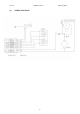
Issue 6 [8] Original Version WIRING DIAGRAM 8 February 2010
Issue 6 Original Version February 2010 [9] Speed Selection Typical cutting speeds (RPM) for various materials Cutter dia 12 13 14 15 16 17 18 19 20 21 22 23 24 25 26 27 28 29 30 31 32 33 34 35 36 37 38 9 239 220 205 191 179 168 159 151 143 136 130 125 119 115 110 106 102 99 95 92 90 87 84 82 80 77 75 Surface speed.
Issue 6 Original Version [10] EXPLODED VIEW OF COMPLETE MACHINE 10 February 2010
Issue 6 Original Version February 2010 [10] Parts list for CM/200/1 & CM/200/3 Item Part No. Component Qty Item Part No. Component Qty 1 1.1 1.2 1.3 1.4 1.5 1.6 2 2.1 2.2 3 3 3.1 3.2 3.3 3.4 3.5 4 4.1 4.2 4.3 4.4 4.5 5 5.1 5.
Issue 6 Original Version [11] EXPLODED VIEW OF GEARBOX AND MOTOR UNITS 12 February 2010
Issue 6 Original Version February 2010 Part list of motor & gearbox(Cobra) Item Part No. Qty Item Part No. 1 RD25521 Motor Assembly (110V) Component 1 6 RD25514 Inner gearplate assembly Component Qty 1 1 RD25523 Motor Assembly (230V) 1 6.1 RD35511 inner gearplate 1 2 See below Armature assembly 1 6.2 RD45522 Bearing 1 3 See below Field coil and motor housing assembly 1 6.3 RD45507 Bearing 1 1.1 RD45530 Socket head cap screw 4 7 RD25507 Clutch assembly 1 1.
Issue 6 Original Version February 2010 [12] PIPE ADAPTOR KIT RD2311 FITTING INSTRUCTIONS Dependent upon the size of the pipe to be cut (see illustrations) attach adjustable angle plates RD3328 with cap screws RD4325 and washers RD4205 (4 off each) to the magnet sides. Do not tighten. Locate the machine on the centreline pipe taking care that the magnet is in line with the longitudinal axis of the pipe. Switch on the magnet and move the sliding plates down to the outside diameter of the pipe.
Issue 6 Original Version February 2010 [13] Tips for keeping your machine in correct working order. In order to ‘get the best life’ out of your Rotabroach machine always keep in good working order. A well maintained machine is a happy machine. A number of items must always be checked on Rotabroach machines. Always before starting any job make sure the machine is in good working order and that there are no damaged or loose parts. Any loose parts must be tightened.
Issue 6 Original Version February 2010 controlled manner, free of lateral movement and vibration. This situation can be maintained by periodic adjustment of the slide and is accomplished in the following manner: 1. Place the machine in an upright position and, by means of the capstan, raise the slide to its highest position. Clean the brass gib strips and apply a small amount of light machine oil to the wear surfaces. 2. Now lower the slide back to its lowest position.
Issue 6 Original Version [14] TROUBLE SHOOTING Magnet and motor do not function Magnet does function, the motor does not Magnet does not function, the motor does Hole cutters break quickly, holes are bigger than the hole cutter Motor running roughly and/or seizing up Motor making a rattling sound Motor humming, big sparks and motor has no force Motor does not start or fails.
Issue 6 Original Version [15] Cutter selection, Speeds and Feeds 18 February 2010
Issue 6 Original Version Notes: 19 February 2010
Issue 6 Original version February 2010 WARRANTY STATEMENT Rotabroach® warrants its machines to be free from faulty materials, or workmanship under normal use for a period of 6 months from initial date of purchase and 90 days for all other parts (excluding cutters), provided that the warranty registration card (or online registration) has been completed and returned to Rotabroach®, or its designated distributor within a period of (30) days from the purchase date, failure to do so will void the warranty.