AXIS 370 Cobra User's manual IBM 3270 Protocol Converter
AXIS 370 Preface Preface Welcome to the AXIS 370 Cobra coax 3270 protocol converter. This manual will guide you through a step-by-step installation procedure. Once installed, the AXIS 370 Cobra works without operator intervention. About Axis Axis Communications is dedicated to provide inventive solutions for network connection of computer peripherals. Since the start in 1984, it has been one of the fastest growing companies in the market.
Preface AXIS 370 About this manual The manual applies to the AXIS 370 Cobra with software release 1.00 and to subsequent releases until otherwise notified. Please refer to the AX-7 Cobra+ Technical Reference Manual for further information of functions and parameters. The manual consists of five sections: 1. INTRODUCTION – The AXIS 370 Cobra and the concepts used in this manual. 2. INSTALLATION – Connecting your AXIS 370 Cobra to the printer and the IBM system. 3.
AXIS 370 Preface Emission Notices USA Europe This equipment generates, uses, and can radiate radio frequency energy and if not installed and used in accordance with the instruction manual, may cause interference to radio communications. It has been tested and found to comply with the limits for a Class A computing device pursuant to Subpart B of Part 15 of FCC rules, which are designed to provide reasonable protection against such interference when operated in a commercial environment.
Table of Contents Table of Contents Section 1 Introduction . . . . . . . . . . . . . . . . . . . . . . . . . . . . . . . . . . . . . . . . . . . . . . . . . . . . . . . 9 The AXIS 370 Cobra . . . . . . . . . . . . . . . . . . . . . . . . . . . . . . . . . . . . . . . . . . . 9 Theory of Operation . . . . . . . . . . . . . . . . . . . . . . . . . . . . . . . . . . . . . . . . . . . 9 ASCII Printer Driver . . . . . . . . . . . . . . . . . . . . . . . . . . . . . . . . . . . . . . . . . . .
Table of Contents Edit Translation Tables . . . . . . . . . . . . . . . . . . . . . . . . . . . . . . . . . . . . . . . . . Character Translation . . . . . . . . . . . . . . . . . . . . . . . . . . . . . . . . . . . . Editing Translation Tables using a Terminal . . . . . . . . . . . . . . . . . . Editing Translation Tables using the System . . . . . . . . . . . . . . . . . . User Definable Strings . . . . . . . . . . . . . . . . . . . . . . . . . . . . . . . . . . . . . . . . .
Table of Contents Appendix C The Front Panel . . . . . . . . . . . . . . . . . . . . . . . . . . . . . . . . . . . . . . . . . . . . . . . . . . . The POWER indicator . . . . . . . . . . . . . . . . . . . . . . . . . . . . . . . . . . . . . . . . . The SYSTEM indicator . . . . . . . . . . . . . . . . . . . . . . . . . . . . . . . . . . . . . . . . . The Rotary Switch . . . . . . . . . . . . . . . . . . . . . . . . . . . . . . . . . . . . . . . . . . . . Start Conditions . . . . . . . . . . . . . . . . . .
Table of Contents This page is intentionally left blank viii AXIS 370 Cobra User’s Manual
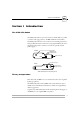
Section 1: Introduction AXIS 370 Section 1 Introduction The AXIS 370 Cobra The AXIS 370 Cobra is a protocol converter, which makes it possible to connect a PC type printer to an IBM mainframe environment. The AXIS 370 Cobra has a coax connector for incoming system data and a parallel Centronics connector for outgoing ASCII data. Power is supplied via the printer's connector or from an optional external power supply.
AXIS 370 Section 1: Introduction ASCII Printer Driver The AXIS 370 Cobra can utilize many of the functions resident in the attached printer, such as bolding, page formatting and paper source selections. The control commands for these functions reside in the Printer Drivers. These cover the standard ASCII emulations such as IBM Proprinter, Epson and HP LaserJet. See Appendix A for a list of available Printer Drivers.
Section 2: Installation Section 2 Installation Unpacking Unpack and check all the items using the following check list. Contact your dealer if anything is missing or damaged. All packing materials are recyclable.
Section 2: Installation Printer Attachment First you establish contact between the AXIS 370 Cobra and the PC type printer. Prepare this by checking that the printer is ready to use. You may also need an optional external power supply, if the printer is unable to supply the AXIS 370 Cobra. 1. Switch off the printer. 2. Connect the AXIS 370 Cobra to the printer, either directly to the parallel printer port, or using the optional printer cable extension and Velcro ribbons. 3.
Section 2: Installation The Generic Printer configuration will support limited printer operation. To get more out of your printer, it is advised to configure the AXIS 370 Cobra for your printer type. Please refer to section 3 before continuing with System Attachment. The test printout will show if the AXIS 370 Cobra has been configured for your printer by the dealer/distributor.
Section 2: Installation System Attachment When your AXIS 370 Cobra is configured, and the configuration is verified by a test printout, it is time to connect it to the IBM system. 1. Switch off the AXIS 370 Cobra by switching off the printer, or, if an external power supply is used, by unplugging the power cord. 2. Set the rotary switch to position ‘0’ (normal print operation). 3. Connect an IBM coax cable leading from the control unit to the AXIS 370 Cobra. 4.
Section 3: Configuration System language Printer driver Emulation Section 3 Configuration To get the most out of your printer, we recommend that you configure your AXIS 370 Cobra for your printer type. Only limited printer operation is supported by the default configuration. Your AXIS 370 Cobra might already have been configured for you. A test printout will verify the current configuration, see Section 2.
System language Printer driver Emulation Section 3: Configuration Configuration from a Terminal The AXIS 370 Cobra is equipped with a menu-driven Configuration Utility. This provides a step-by-step method to adapt the AXIS 370 Cobra to your IBM coax host and printer. Follow these steps to start the configuration: 1. Switch off the AXIS 370 Cobra. If the power is taken from an attached printer, then switch the printer off. If you are using an external power supply, unplug the power cord. 2.
Section 3: Configuration System language Printer driver Emulation Key Definitions ========================================================================= AXIS 370 Cobra Ver 1.00 960103 ========================================================================= KEY DEFINITIONS _Right Left Up Down Enter Assign cursor keys (c) AXIS COMMUNICATIONS AB 1996 The first menu is for assigning the specific keys to be used in the configuration. No other keys than the five assigned can be used.
System language Printer driver Emulation Section 3: Configuration Basic Configuration ========================================================================= AXIS 370 Cobra Ver 1.
Section 3: Configuration Select Printer Driver System language Printer driver Emulation This submenu is shown after you have selected ‘Basic Configuration’ in the Main Menu.
System language Printer driver Emulation Section 3: Configuration Select IBM Printer Emulation This submenu is shown after you have selected Printer Driver.
Section 3: Configuration Select System Language System language Printer driver Emulation This submenu is shown after you have selected IBM Printer Emulation.
System language Printer driver Emulation Section 3: Configuration Select Form Length This submenu is shown after you have selected System Language. ========================================================================= BASIC CONFIGURATION ========================================================================= FORM LENGTH 072 Use cursor keys to edit, to select This is the number of lines per page.
Section 3: Configuration Select Lines per Inch (LPI) System language Printer driver Emulation This submenu is shown after you have selected Form Length. ========================================================================= BASIC CONFIGURATION ========================================================================= LINES PER INCH 3 4 6 8 Off Use to move, to select This is the line spacing of the printout. The default is 6 Lines per Inch.
System language Printer driver Emulation Section 3: Configuration Select Characters per Inch (CPI) This submenu is shown after you have selected LPI. ========================================================================= BASIC CONFIGURATION ========================================================================= CHARACTERS PER INCH 5 10 12 15 17 Proportional Off Use to move, to select This is the character spacing of the printout. The default is 10 Characters per Inch.
Section 3: Configuration System language Printer driver Emulation Save the Configuration Select ‘Save’ in the Main Menu. The following submenu is shown: ========================================================================= SAVE ========================================================================= SAVE SETTINGS PERMANENTLY Yes No Use to move, to select Select ‘Yes’ to save the current configuration permanently. The system indicator stops flashing while save is in progress.
System language Printer driver Emulation Section 3: Configuration Exit the Configuration Select ‘Exit’ in the Main Menu. The following submenu is shown: ========================================================================= SAVE ========================================================================= EXIT CONFIGURATION Yes No Use to move, to select Select ‘Yes’ to exit the configuration. The Configuration Utility is terminated and the screen is left blank.
Section 4: Advanced Functions 1001010100111 11010001001 010011101 Section 4 Advanced Functions The AXIS 370 Cobra supports a number of functions beyond standard IBM printer operation. During normal mode of operation, AXIS 370 Cobra, together with your printer, emulates the IBM coax printer selected in your configuration. In addition, the Extended Emulation Mode gives you access to functions not available in standard IBM printers.
1001010100111 11010001001 010011101 Section 4: Advanced Functions Main Menu A number of the advanced functions can be programmed or edited using Configuration from a Terminal. The Main Menu is displayed when the configuration is started (See “Configuration from a Terminal” on page 16). ========================================================================= AXIS 370 Cobra Ver 1.
Section 4: Advanced Functions 1001010100111 11010001001 010011101 Configuration from the System This function allows you to configure the AXIS 370 Cobra without using the Configuration from a Terminal as described in Section 3 By inserting configuration commands in your document, the AXIS 370 Cobra can be tailored to meet special requirements for your print jobs.
1001010100111 11010001001 010011101 Section 4: Advanced Functions Transparency The Transparency function allows you to send data directly to your printer without any conversion (pass-through). The data could be ASCII printer commands unsupported by the interface (e.g. underlined text), or even down-loaded fonts. There are two types of Transparency, Single-byte and Multi-byte. The function is accessed in Extended Emulation Mode.
Section 4: Advanced Functions 1001010100111 11010001001 010011101 Redefine Configuration and Transparency Sequences The Start and Stop Transparency and Configuration are controlled by three string parameters: • • • Transparency Lead-In Sequence (#070), default ‘%%’. Configuration Lead-In Sequence (#071), default ‘%P’. Transparency/Configuration Trailer Sequence (#072), default ‘%’. See Appendix A for a description of the parameters. The parameters can be redefined using Configuration from the System.
1001010100111 11010001001 010011101 Section 4: Advanced Functions Edit Translation Tables Normally, there is no need to edit the translation tables. The character translation tables activated by the Printer Driver and System Language selections are designed to produce the same printouts as the emulated IBM printer. If you should need to make further adjustments, this section explains the character translation process and how to modify the translation tables to meet specific needs.
Section 4: Advanced Functions Editing Translation Tables using a Terminal 1001010100111 11010001001 010011101 Start the Configuration from a Terminal as described in Section 3. Select the Character Translation entry in the Main Menu.
1001010100111 11010001001 010011101 Section 4: Advanced Functions ========================================================================= VIEW/EDIT DBC TO ASCII TABLE ========================================================================= ASCII Char.
Section 4: Advanced Functions 1001010100111 11010001001 010011101 Example 1: To change a left bracket ‘[’ at position 0A to a left bracket ‘{’ which has ASCII value $7B. 1. Move the highlight to position 0A in the table. 2. Press Enter to edit. The row above the help message contains the edit field. This field shows the current DBC position and the corresponding ASCII value.
1001010100111 11010001001 010011101 Section 4: Advanced Functions Example 2: Change the overscored semicolon ‘;’ at position 9E to a ‘bullet’ character ‘•’ which has ASCII value $FA: 1. Move the highlight to position 9E in the table. The three asterisks indicate that this DBC character translates to a string rather than a single character. 2. Press Enter.
Section 4: Advanced Functions Editing Translation Tables using the System The translation table can be modified from the system.
1001010100111 11010001001 010011101 Section 4: Advanced Functions User Definable Strings The User Definable Strings is a set of 255 strings at your disposal. A common application is to program and store various printer control commands, and send them to the printer using string references rather than the commands themselves. Please refer to the manual for your PC type printer for information on ASCII printer commands.
Section 4: Advanced Functions 1001010100111 11010001001 010011101 Example (IBM Proprinter): You want to store commands for underlining text. If you have an IBM Proprinter, ‘start underline’ and ‘stop underline’ are defined by the ASCII codes $1B,$2D,$31 and $1B,$2D,$30 respectively. 1. When string number $01 is highlighted, press Right to enter edit mode. The string is set to $00. 2. Edit the string to $1B,$2D,$31 using the cursor keys (press Right to expand the string). 3. Press Enter. 4.
1001010100111 11010001001 010011101 Section 4: Advanced Functions Programming Strings from the System Document Example (See also previous section): Assume that you have an IBM Proprinter: %P =209,$00 =209,$01,$1B,$2D,$31 =209,$02,$1B,$2D,$30 =207,10 =207,12 % Note: (Configuration lead-in sequence) (Delete all) (Program string 01 to ‘start underline’) (Program string 02 to ‘stop underline’) (Initialize settings) (Save settings permanently) (Configuration trailer sequence) ❏ Strings are programmed in Ex
Section 4: Advanced Functions 1001010100111 11010001001 010011101 String Substitutions This function is useful when you want to print a document that is prepared for a different PC type printer than yours. The document contains control commands for a specific printer, and you have to convert these commands in order to print this document with your printer. Instead of changing the document, you can let the AXIS 370 Cobra do the conversion for you by using String Substitution.
1001010100111 11010001001 010011101 Section 4: Advanced Functions Programming String Substitutions from a Terminal Start the Configuration from Terminal as described in Section 3. 1. Select the String Substitutions entry in the Main Menu. The String Substitutions Menu consists of pairs of Match and Substitute strings. 2. Edit the first two string pairs. See “User Definable Strings” on page 38 on how to edit strings.
Section 4: Advanced Functions The same programming example as above can also be obtained by inserting the following lines into your document: Programming String Substitutions from the System %P =210,$00 =210,$01,$1B,$2D,$31 =210,$02,$1B,$26,$64,$44 =210,$03,$1B,$2D,$30 =210,$04,$1B,$26,$64,$40 =207,10 =207,12 % Note: 1001010100111 11010001001 010011101 (Configuration lead-in sequence) (Delete all) (Start underline - Proprinter) (Start underline - HP LaserJet) (Stop underline - Proprinter) (Stop underl
1001010100111 11010001001 010011101 Section 4: Advanced Functions Bar Codes This function gives you easy access to a range of standard bar code types. You can design every single bar code printout to meet your specific requirements, such as width and height. There are two functions and two parameters that are used for printing bar codes: • • • • Function ‘211’ defines the bar code. Function ‘212’ prints the bar code. Bar Code Driver (#093). Bar Code Attributes (#094).
Section 4: Advanced Functions 1001010100111 11010001001 010011101 value 4: Human Readable Text. Selectable values: 0 = No textline below the bar code 1 = Human readable textline below the bar code. 2 = Human readable textline below the bar code with empty line in between. value 5: Horizontal Bar Code Start Position in 1/12 inch steps. The value may range from 1 to 255 (in decimal).
1001010100111 11010001001 010011101 Section 4: Advanced Functions Automatic Page Orientation Note: ❏ This section applies to Laser Printer drivers only.
Section 5: Solving Problems Section 5 Solving Problems This section helps you to solve any problems that might arise when installing or using your AXIS 370 Cobra interface. There are two major areas of difficulty: • Missing printouts • Incorrect printouts Use the following checklists to pinpoint the possible cause. If your problems should continue, please contact your dealer/distributor. Missing Printouts In case of missing printout, check the following: 1.
Section 5: Solving Problems Incorrect Host Printouts There are five major types of incorrect printouts: Some Characters are Printed Incorrectly • Characters like ä ü Ä Ü are printed as { } [ ] Most likely an incorrect System Language has been selected. Select the System Language matching your system configuration, or ‘Load Translate table’ to make your Control Unit down-load the System Language for you. See “Select System Language” on page 21.
Section 5: Solving Problems Lost characters at end of line Some laser printers cannot print a full line of 80 characters in 10 CPI. Change the Characters per Inch setting to 12 CPI. Advanced users: You might also modify the 10 CPI string contents to set 10.2 CPI instead. Additional empty lines or spaces Your system application may assume the utilization of an IBM RPQ. Several empty lines can be caused by an incorrect logical buffer size.
Section 5: Solving Problems Reporting Problems If you run into problems that you can’t solve on your own, it is important that you make an error report for your System Manager or distributor. The error report should include: • A printout with a description of the errors • If possible, a correct printout • A Parameter List • A System and ASCII hexdump If you need technical support, please contact your dealer. If they can’t help you, they will forward your request through the appropriate channels.
Section 5: Solving Problems Producing Hexdumps A hexdump is a printout where the input data stream is printed as hexadecimal byte values rather than being interpreted as characters and control codes. The AXIS 370 Cobra features two different types of hexdump modes: • System hexdump This mode will trap the input data before the character and control code conversion. The data is printed as EBCDIC or DBC hexadecimal values.
Section 5: Solving Problems Error messages There are five different error conditions that will cause the AXIS 370 Cobra to print an error message on your printer: E2-PERMANENT MEMORY CHECKSUM ERROR, FACTORY DEFAULTS SET This message indicates that the non-volatile memory has been corrupted. The interface is automatically set to factory default state (your configuration is lost). If the message does not re-appear after power-off/power-on, configure the AXIS 370 Cobra (Section 3).
Appendix A: The Parameter List Appendix A The Parameter List The Parameter List shows the complete configuration of the AXIS 370 Cobra. Each parameter contains a value or string that is used to determine how the AXIS 370 Cobra should behave towards the host and towards the printer. In this appendix you will find a selection of parameters, i.e. the Basic Configuration, Please refer to the AX-7 Cobra+Technical Reference Manual for parameters not covered by this manual.
Appendix A: The Parameter List Printer Drivers A printer driver is a device driver containing all the parameters required to drive a particular range of printers.
Appendix A: The Parameter List #004 Character Density Number of characters per inch (CPI). Value #005 Description Value Description 0 Do not set Char. Density 15 15 Characters per Inch 5 5 Characters per Inch 17 16.7 Characters per Inch * 10 10 Characters per Inch (default) 99 Proportional Char. spacing 12 12 Characters per Inch - - System Language This parameter makes the EBCDIC-to-DBC translation table match the System Language configuration of your IBM system.
Appendix A: The Parameter List #040 Extended Emulation Mode Selects the default Extended Emulation Mode. #041 Value Description *0 No Extended Emulation Mode (default) Value 3 Description MPI compatible mode 1 Escape Character translates to ASCII $1B 4 Memorex 2068 compatible mode 2 Standard Extended Emulation Mode 5 Maersk Data compatible mode Escape Character Select the DBC character code used for Single-byte Transparency, User Definable Strings and Extended Emulation Mode 1.
Appendix A: The Parameter List #042 Option Select 1 This parameter controls 8 independent switches. Each bit represents one switch. Value Description Value Description $00-$FF (valid range) *$02 (default) Bit 1 ($02): LU1 Form Feed valid in 1st line. Value Description Value Description 0 No *1 Yes (default) Bit 3 ($08): SHF Maximum Print Position select.
Appendix A: The Parameter List #063 ASCII Character Set Selects the DBC to ASCII translation table.
Appendix A: The Parameter List #066 Option Select 2 This parameter controls 8 independent switches. Each bit represents one switch. Value Description Value Description $00-$FF (valid range) *$10 (default) Bit 0 ($01): Extended Emulation Control Syntax. Value Description Value Description *0 Normal syntax (default) 1 Only Escape Character after ‘&&??’ Bit 1 ($02): True Screen Image in Host Direct Mode.
Appendix A: The Parameter List #071 Configuration Lead-In Sequence Starts Configuration Mode. #072 Value Description Value Description (any length or content) *$2E $AF ‘%P’ (default) Transparency/Configuration Trailer Sequence Terminates the Multi-byte and Configuration Modes. #074 Value Description Value Description
Appendix A: The Parameter List #094 Bar Code Attributes Adjust bar code printout quality to paper and printer conditions. #100 Value Description Value *0 Normal (default) 2 Description Bold 1 Thin 3 Thin and Bold Option Select 3 This parameter controls 8 independent switches. Each bit represents one switch. Value Description Value Description $00-$FF (valid range) *$02 (default) Bit 0 ($01): Next print position after LU3 Form Feed within Print Buffer.
Appendix A: The Parameter List #124 Extended Attribute Buffer (EAB) Controls the EAB and APL text emulation. The default value depends on the selected Printer Driver. #139 Value Description Value Description 0 EAB and APL disabled 2 Use EAB, APL characters are emulated by PC Set 2 Characters 1 Use EAB, print APL characters as normal characters - End of Job Time-out A timer controlling parameters #140 and #151 when the host has been idle for the specified amount of time.
Appendix A: The Parameter List #143 GDDM Color Selects Color/Monochrome GDDM graphics. #148 Value Description Value Description *0 Monochrome (default) 2 Seven colors 1 Four colors Orientation Controls the page orientation when automatic orientation is disabled, or when the calculated page size does not fit within the physical page size.
Appendix A: The Parameter List This page is intentionally left blank 64 AXIS 370 Cobra User’s Manual
Appendix B: DBC Character Table Appendix B õ ê ÿ î DBC Character Table This table (DBC - Device Buffer Code) shows the internal character representation in the AXIS 370 Cobra. 0 1 2 3 4 5 6 7 8 9 A B C D E F 0 Nul EM FF NL – CR – – > < [ ] ) ( } { 1 SP = ' " / \ I I ? ! $ ¢ £ ¥ Pt ¤ 2 0 1 2 3 4 5 6 7 8 9 ß § # @ % _ 3 & .
901 456 23 Appendix C: The Front Panel 78 Appendix C The Front Panel The front panel has two indicators (POWER and SYSTEM) and a rotary switch. The switch is used for accessing certain functions. In normal print operation it should be set to '0'. The POWER indicator This indicator (green) is lit when the AXIS 370 Cobra is switched on. The SYSTEM indicator This indicator (green) is lit when the AXIS 370 Cobra is connected to your IBM system.
901 23 456 Appendix C: The Front Panel 78 Start Conditions The action when the AXIS 370 Cobra is switched on will be determined by the setting of the rotary switch, as follows: Pos. Description 0 Normal print operation. * 1-7 Reserved. 8-9 Perform a test printout, then start normal print operation. * If a terminal is connected the terminal set-up routine is started automatically, see Section 3. Test Mode Test Mode is reached from normal print operation.
Appendix D Updating the Software Appendix D Software that can be Updated Checking if an update is available • Updating the Software The AXIS 370 Cobra software held in Flash ROM All software updates are free of charge. Contact your dealer to check if there has been any new issues of the software. You should have your present version numbers ready to compare against the latest software issues from Axis. Alternatively you may wish to check the Axis WWW Home Page at http://www.axis.
Appendix E: Technical Specification Appendix E Host Environments IBM System Features Technical Specification • • • • • • IBM S/370, S/390 IBM 303x, 308x, 309x IBM 81xx IBM 47xx IBM 43xx IBM 937x • • • • • • • • • IBM 3174 IBM 3274 type A IBM 3276 IBM 8775 Display Terminal IBM 4701/4702 Device Cluster IBM 4300 Printer Adapter IBM 9370 Subsystem Control Unit IBM 3299 Multiplexor Equivalent PCM Control Units • • • • • • IBM 3287 mod. 1 and 2C IBM 3268 mod. 1 and 2 IBM 4214 mod. 1 IBM 3262 mod.
Appendix E: Technical Specification Axis 370 Cobra Additional Features Hardware Specifications Approvals • • • • • • • • • • Configuration from a Terminal or from the System 12 predefined Printer Drivers, fully editable Fully editable Character Translation Tables 255 User Definable Strings 127 String Substitutions Programmable Transparency Function (data pass-through) Bar Codes Start/End of Job Strings Automatic Page Orientation and COR FLASH memory Size: 29x55x100 mm / 1.2"x2.2"x4.0" Weight: 0.
Appendix F: Related Documentation Appendix F Related Documentation Title Part Number AX-7 Cobra+ Technical Reference 12937 IBM 3274 Control Unit Customizing Guide GA23-0065-6 IBM 3174 Subsystem Control Unit Customizing Guide GA23-0214-1 IBM 3174 Character Set Reference GA27-3831-04 IBM 3287 Printer Models 1C and 2C Components Description GA27-3229-2 IBM 3268 Printer Models 2 and 2C Description GA27-3268-2 IBM 4214 Printer Model 1 Product Description GC31-2563-1 IBM 3262 Printer Models 3 an
Index Index Numerics 204 Translate EBCDIC to DBC 37 205 Translate DBC to ASCII 37 207 Multi-purpose Function 29 209 User Definable Strings 40 210 String Substitiutions 43 211 Define Bar Code 44 212 Print Bar Code 45 A Anonymous FTP 50 ASCII Character Set 58 Automatic Orientation 60 Axis WWW Home Page 50 B Bar Code Attributes 44, 61 Defining 44 Driver 44, 60 Example 45 Printing 45 C Character Density 55 Characters per Inch 24 Configuration Exiting 26 Lead-In Sequence 31, 60 Saving 25 Start 29 start 15 Tr
Index extended emulation mode enter 29 exit 29 functions in 27 N Normal emulation mode operation 27 normal emulation mode resume 29 F Flash ROM 68 Form Length 22, 54 G O Option Select 1 57 Option Select 2 59 Option Select 3 61 Orientation 63 GDDM Color 63 GDDM Support 62 P H Hexdump 51 I IBM Printer Emulation 10, 20, 57 Internet 50 Internet Axis Home Page 50 L Line Density 54 Lines per Inch 23 LU1 32 LU3 32 M Multi-byte transparency 30 AXIS 370 Cobra User’s Manual v.
Index Parameters (Continued) #124 Extended Attribute Buffer (EAB) 62 #139 End of Job Time-out 62 #140 End of Job Sequence 62 #142 GDDM Support 62 #143 GDDM Color 63 #148 Orientation 63 #151 Start of Job Sequence 63 #157 Disconnect if Power off 63 List of 54 Printing list of 50 Part numbers 11 pass-through 30 POWER indicator 12, 14, 47, 66 Printer Attachment 12 Printer Driver 10, 54 Printer driver 19 T Test Mode 67 Test printout 12 Translation Table 32 Translation tables 32 Transparency 30 Lead-In Sequence