
Specifications

ASSEMBLY INSTRUCTIONS
PLEASE READ CAREFULLY BEFORE PROCEEDING!
NOTICE
This device will operate as advertised when properly constructed, installed, and adjusted.
CBC INTERNATIONAL has no control over the skill of the purchaser; therefore no warranty can
be given. We will repair units built only from our own kits for $25 prepaid with the returned unit.
NO BASKET CASES PLEASE!
This device is intended for educational purposes, 10-Meter Amateur use, or 27 MHz receivers
only. Supplier assumes no liability for improper or illegal use.
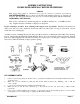
Proper soldering is essential. Poor soldering is the biggest cause of problems. Finished joints should look
shiny, never dull. Use only a small iron (25-45 watt) with a very fine round or slot tip to avoid shorts. See the
sketch below for soldering tips.
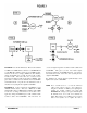
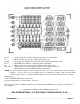
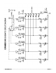
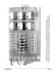
Assembly consists of stuffing the parts into the proper PC board holes, as illustrated in the X-Ray View drawing,
Page 8. Check against the Schematic Circuit Diagram (Page 9) if you’re in doubt about the correct holes. Push all
parts down tight, wiggling back and forth if necessary as you press down. See the photo on Page 10. The diodes
and resistors will bend naturally to the proper hole spacing.
KIT ASSEMBLY NOTES
1. Observe correct diode polarity; the banded end is [—] and must be installed in the holes marked with the banded end
on the PC board.
2. Make sure you don’t mistake C7 (.001 µF) with C1-C6, which are all .01 µF. Markings: “102” = .001 µF,
“103” = .01 µF.
3. L1-L7 are not polarized and can be installed with leads either way.
4. Make sure the “A” and “B” wire connections go to the cold side and hot side of the radio’s oscillator circuit,
respectively.
5. Don’t forget to install a trimmer, fixed capacitor, or bare jumper wire in the CT1-CT6 positions (or however many
crystal positions you’re actually using) to complete the RF circuit continuity.
___________________________________________________________________________________________________
EXPANDER 240 PAGE 2