
Specifications
INSTALLATION
NOTE: The radio’s tuned circuits may need realignment
after installation of the EXPANDER 240. Much
depends upon the desired center operating frequency
of the expanded radio. Therefore a schematic
diagram of the radio is essential, as well as an
accurate Frequency Counter. Although specific
installation points are described for some popular
models, the work should be done by a qualified
electronic technician. The supplier assumes no
liability for damage to any equipment resulting from
improper installation.
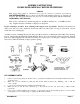
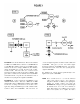
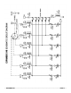
Refer to FIGURE 1 on the next page for the general
connection points. Remember, you must check the radio’s
schematic for the exact location. The “Xs” show where you’ll
be breaking the existing signal path to inject your own new
mixing frequencies. In all cases, make sure you install the
EXPANDER 240 wires coming from its “A” and “B” holes to
the correct empty PC foils left by the crystal you removed
from the radio: “A” is the cold or ground side, and “B” is the
hot side of the oscillator.
Mount the EXPANDER 240 as physically close to the radio’s
crystal as possible to avoid problems with long leads from the
“A” and “B” hole wires. Then you can run the ribbon cable
any convenient length to where you’ve actually mounted your
hard switch. The “GND” symbol hole above the “6” hole on
the PC board must be tied to the chassis common point of the
radio to avoid ground loops. This radio ground point is the
same one used for, among other things, the metal shield cans
on the tuning transformers. You can solder the BLACK wire
to the nearest metal tuning coil using the shortest wire length
possible. Connect the RED wire through your switch pole
common to a constant regulated DC source of +7-10 VDC;
all CBs will have at least one of these available somewhere in
the power supply distribution chain.
GENERAL INSTALLATION BY CHASSIS TYPE
Radios to be expanded can be classified into three general
categories:
TYPE 1: All crystal-synthesized 23-channel AM or
AM/SSB models.
TYPE 2: All AM or AM/SSB PLL types having a crystal
oscillator loop mixing stage which is doubled or
tripled by subsequent tuned circuits.
TYPE 3 All AM or AM/SSB PLL types having a fixed
crystal oscillator loop mixing stage operating
directly at the crystal frequency.
TYPE 1 INSTALLATION — All 23-Channel AM or
AM/SSB Crystal-Synthesized Radios
See FIGURE 1. These radios all use banks of crystals that
mix together, most often in the 6-4-4 or 6-4-2
configurations. The most common AM schemes use the 37
MHz plus separate 10 MHz banks each for RX and TX
(FIGURE 1-A), or the 23 MHz/14 MHz plus separate
11 MHz RX and TX Local Oscillators (FIGURE 1-B).
AM/SSB radios generally use crystals in the 7.8 MHz or 11
MHz range for this bank.
Note that the SSB types also have crystals in the
Carrier Oscillator and synthesizer stages to provide the SSB
mode offsets. But these crystals will have no effect on the
location of the EXPANDER 240.
The crystals to be added will go in the bank containing the six
mixing crystals, regardless of whether the radio is AM or
AM/SSB. These six crystals always mix to control the
following six continuous channel groups:
Channels 1, 2, 3, 4
Channels 5, 6, 7, 8
Channels 9, 10, 11, 12
Channels 13, 14, 15, 16
Channels 17, 18, 19, 20
Channels 21, 22, 23
Remove one of the six crystals from the radio and place it in
the “X1” crystal position of the EXPANDER 240 instead. To
make it easy to remember which Channel Selector positions
provide which new channels, you should remove either the
lowest or the highest frequency mixing crystal, depending
upon whether you are expanding the radio below Ch. 1 or
above Ch. 23. Observe the correct hot and cold crystal
connections, as noted above.
For 10-Meter conversions there are two possibilities. You’ll
either remove the highest radio crystal and add the five extras,
or you’ll replace all six in addition to those in the
EXPANDER 240, for a total of 43 consecutive channels.
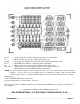
Install your new crystals in the remaining #2-#5 positions of
the EXPANDER 240. Put them in the correct order (#2, #3,
#4, #5, #6) so that your chosen switch makes the frequency
bands continuous. Since you’re adding up to five extra
crystals, and each one will be mixed in the radio with four
others, this means you will get a total of twenty additional
new channels.
Using a 12" piece of hookup wire (provided in our kits); cut it
in half and place the two pieces in the “A” and “B” holes of
the EXPANDER 240. Install the two loose wire ends from
holes “A” and “B” in the two now-empty holes where you
removed the mixing crystal, being sure to put the “A” wire in
the low or ground side hole, and the “B” wire in the hot or
oscillator side hole of the radio.
___________________________________________________________________________________________________
EXPANDER 240 PAGE 4