MODELS: M51SPH MX51SPH COBRA LAWN MOWER OWNER’S MANUAL Cobra Garden Machinery Henton and Chattell Ltd., London Road, Nottingham NG2 3HW UK www.cobragarden.co.
CONTENTS SECTION 1 SYMBOLS MARKED ON THE PRODUCT……………………………3 SECTION 2 GENERAL SAFETY RULES…………………………………………….3 SECTION 3 PARTS DESCRIPTION………………………………..…………….…..6 SECTION 4 TECHNICAL DATA…………………………………………………...…..7 SECTION 5 ASSEMBLY…………………………………………………………….….7 SECTION 6 “3 IN 1”……………………………………………………………….…....10 SECTION 7 OPERATION INSTRUCTIONS……………………………………..…..12 SECTION 8 MAINTENANCE INSTRUCTIONS ……………………………..……...15 SECTION 9 LUBRICATION INSTRUCTIONS …………………………………..….
WARNING: For your own safety please read this manual before attempting to operate your new unit. Failure to follow instructions can result in serious personal injury. Spend a few moments to familiarise yourself with your mower before each use. 1. SYMBOLS MARKED ON THE PRODUCT Fig. A B.1 Read Operator's Manual. B.2 Keep bystanders away. B.3 Pay attention to the operator's hands and feet to avoid injury. B.4 Fuel is flammable. Do not add fuel with running machine. B.
Training 1. Before using the lawnmower read the instructions carefully. Familiarise yourself with the controls and pay particular attention in learning how to stop the machine in an emergency. 2. Never allow children or people unfamiliar with these instructions to use the lawn mower. Local regulations can restrict the age of the operator. 3. Never mow while people, especially children or pets are nearby. 4.
19. Stop the engine and disconnect the spark plug wire, make sure that all moving parts have come to a complete stop and, where a key is fitted remove the key, make sure engine has had time to cool: - Before unclogging the chute and clearing blockages. - Before checking, cleaning or working on the lawn mower. - After striking a foreign object. Inspect the lawnmower for damage and make repairs before restarting. - If the lawn mower starts to vibrate abnormally (check immediately). 20.
3. PARTS DESCRIPTION Fig.C MX51SPH 1. Upper handle 2. Starter handle 3. Rope Guide 4. Locking Lever 5. Grass catcher 6. Height adjusting lever 7. Deck 8. Sideward flap 9. Spark Plug 10. Oil Cap 11. Fuel cap 12. Cable-clamp 13. Choke Lever 14. Brake control handle 15. Self-drive control handle 16. Mulching wedge 17. Discharge channel Including a spark plug wrench Fig. H M51SPH 1. Upper handle 2. Self-drive control handle 3. Starter handle 4. Rope Guide 5. Locking Lever 6.
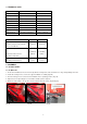
4. TECHNICAL DATA Model M51SPH MX51SPH Engine Series & type GCV160 GCV160 yes yes Engine Displacement 160 cm³ 160 cm³ Blade Width 510mm 510mm Rated Speed 2800/min 2800/min 0.91 L 0.91 L 60L 60L 34.7kg 36 kg Self-Propelled Fuel Tank Capacity Grass catcher capacity Net Weight Height adjustment: 25~70mm, 10 adjustment Model 25~75mm, 7 adjustment M51SPH MX51SPH Guaranteed Sound pressure level at the 84.5dB (A) 84.
Fig.1D Fig.1G Fig.1E Fig.1F Fig.1H For the M51SPH 1. Fix the lower handlebars into the unit mower with a suitable spanner. (Fig.1J/Fig.1K/Fig.1L) 2. Lift the two locking levers to release the upper handlebars for folding. (Fig. 1M) 3. Push the locking lever closed to lock the handlebars in the operating position. (Fig.1N) 4. Adjust the tension by turning the lock nut with a suitable spanner. (Fig.1O) 5. Attach the cable-clamp to the position shown and then attach the cable. (Fig.1P) Fig.1J Fig.
5.2 ADJUSTMENT FOR AN APPROPRIATE ANGLE For MX51SPH A).Pull the locking lever open on both sides of the handle. B).Adjust the angle of the handle by raising or lowering as required. The angle can be adjusted by -20º to 20º as the Fig.2 shows C).Push the locking lever closed to connect the lower handle and the upper handle. Fig.2 5.3 MOUNTING AND DISMOUNTING THE GRASS CATCHER 1. To fit: Raise the rear cover and hitch the grass catcher on rear of the mower. 2.
5.6 Tool Box For the MX51SPH This MX51SPH lawn mower has a tool box. Push the button to open it, and then press the cover to lock it. You can put tools such as spanners and screwdrivers in this box. Fig.6 Starting Operation 6. “3 IN 1” The lawn mower has 3 in 1 features: 1. Rear grass collection. 2. Grass mulching. 3. Side-discharge.
TWO: Resetting for side-discharge mowing 1. Lift the rear cover and remove the grass catcher. 2. Mount the discharge channel. 3. Lift the sideward flap for side discharge (Fig.7D) 4. Mount the discharge guide for side discharge on the support pin of the sideward flap. (Fig.7E/Fig.7F) 5. Lower the sideward flap- the flap lies on the discharge channel. (Fig.7G) WARNING: Only when the engine and the blade are at standstill! Fig. 7D Fig. 7F Fig. 7E Fig.
7. OPERATING INSTRUCTIONS 7.1 BEFORE STARTING Service the engine with petrol and oil as instructed in the separate engine manual packed with your mower. Read all instructions carefully. WARNING! Petrol is highly flammable. Store fuel in containers specifically designed for this purpose. Refuel outdoors only, before starting the engine and do not smoke while refueling or handling fuel. Never remove the cap of the fuel tank or add petrol while the engine is running or when the engine is hot.
Start the engine carefully according to the instructions and with feet well away from the blade. Do not tilt the lawn mower when starting the engine. Start the mower on a level surface, free of high grass or obstacles. Keep hands and feet away from the rotating parts. Do not start the engine when standing in front of the discharge opening. 7.3 OPERATION PROCEDURES During operation, tightly hold the brake handle with both hands.
will also help to clean up any stray clippings left on the lawn. The mower should always be operated at full throttle to get the best cut and allow it to do the most effective job of mowing. Clean underside of deck: Be certain to clean the underside of the cutting deck after each use to avoid a build-up of grass, which could prevent proper mulching. WARNING: If the mower blade strikes a foreign object, stop the engine immediately.
For the M51SPH Your mower is equipped with a central height adjustment lever offering 10 height positions. The height (the blade to the ground) can be adjusted from 25 mm (position 1) to 70 mm (position 10). Fig.12A Fig.12B 1. Stop the mower and disconnect the spark plug cable before changing the mower cutting height. 2. The central height adjustment lever offers you 10 different height positions. 3.
Fig.13A NOTE: Replace the filter if frayed, torn, damaged or unable to be cleaned. 10.2 CUTTING BLADE CAUTION: Be sure to disconnect and ground the spark plug wire before working on the cutting blade to prevent accidental engine starting. Protect hands by using heavy gloves or a rag to grasp the cutting blades. Tip the mower as specified in the separate engine manual. Remove the hex bolt and washer, which holds the blade and blade adapter to the engine crankshaft.
When you change the blade, use the original type marked on the blade: Cobra Part Number 263001330, to order the blade, please contact your local dealer) WARNING: Do not touch the blade whilst it is still rotating. 10.4 ENGINE Refer to the separate engine manual for engine maintenance instructions. Maintain engine oil as instructed in the separate engine manual packed with your unit. Read and follow the engine instructions carefully. Service the air filter as per the separate engine manual.
12 TROUBLES SHOOTING PROBLEM Engine does not start. PROBABLE CAUSE Throttle chock not in the correct position for the prevailing conditions. Fuel tank is empty. Air cleaner element is dirty. Spark plug loose. Spark plug wire loose or disconnected from plug. Spark plug gap is incorrect. Spark plug is defective Carburetor is flooded with fuel Engine difficult to start or loses power. Engine operates erratically. Faulty ignition module Dirt, water, or stale fuel tank. Vent hole in fuel tank cap is plugged.
13. WARRANTY This product is warranted in accordance with legal regulations for a 24 month period effective from the date of purchase by the first user. This product will not be covered if used in a commercial application.
15. EC-DECLARATION OF CONFORMITY EC Declaration of Conformity We herewith declare, Cobra Garden Machinery Henton & Chattell Ltd, London Road, Nottingham NG2 3HW UK That the following machine complies with the appropriate basic safety and health requirements of the EC Directive based on its design and type, as brought into circulation by us.