FABCO POWER 845-469-9151 Fax: 845-469-7871 PO BOX 582 CHESTER NY 10918 WWW.FABCOPOWER.COM Email: mail@fabcopower.com EAGLE 6 IN 1 POWER STATION OPERATORS, MAINTENANCE AND PARTS MANUAL P/N: 308276 03/24/2010 CRH Mfg.
CAUTION If this System is used in less then 1 ½ Hour operations You must change the Air end Hydr.Oil every 30 Days. Using this System in short periods less than 1 Hour will create moister in the Hydraulic Oil and will damage the Air End beyond repair. By changing the Oil every 30 Days this damage will be avoided. Damage to the Air End is NOT covered under the Warranty.
OPERATORS, MAINTENANCE, AND PARTS MANUAL EAGLE 6 IN 1 Operation & Maintenance Section TABLE OF CONTENTS Operation & Maintenance Section Specifications ...................................................................................................................... 6 Safety .................................................................................................................................. 7 Compressor Terminology ............................................................................
SPECIFICATIONS CFM 30 PSI 110 GENERATOR MAX OUTPUT V OLTS 120/240 WELD ER MAX OUTPUT AMPS 300 C OM P RE S S OR D E L IV E RY F L UID C A PA C ITY - C OM P RE S S OR ( N O T H YD R A U L IC ) 2 . 0 G A L L O N S YS TE M .75 COMPRESSOR SUMP H YD R A U L IC D E L IV E R Y 25 GPM @2000 PSI C O M P O N E N TS S YS TE M OV E RA L L D IM E NS IONS (SEE BELOW) W E IGHT ( W E T) 475LBS.
SAFETY WARNING ALL UNITS ARE SHIPPED WITH A DETAILED OPERATORS AND PARTS MANUAL. THIS MANUAL CONTAINS VITAL INFORMATION FOR THE SAFE USE AND EFFICIENT OPERATION OF THIS UNIT. CAREFULLY READ THE OPERATORS MANUAL BEFORE STARTING THE UNIT. FAILURE TO ADHERE TO THE INSTRUCTIONS COULD RESUL T IN SERIOUS BODILY INJURY OR PROPERTY DAMAGE. AIR COMPRESSOR SAFETY PRECAUTIONS Safety is basically common sense.
SAFETY DANGER DO NOT USE FABCOs COMPRESSOR SYSTEMS TO PROVIDE BREATHING AIR. SUCH USAGE,WHETHER SUPPLIED IMMEDIATELY FROM THE COMPRESSOR SOURCE, OR SUPPLIED TO BREATHING TANKS FOR SUBSEQUENT USE, CAN CAUSE SERIOUS BODILY INJURY. BOSS INDUSTRIES, INC. DISCLAIMSANY AND ALL LIABILITIES FOR DAMAGE FOR LOSS DUE T O PERSONAL INJURIES, INCLUDING DEATH, AND/OR PROPERTY DAMAGE INCLUDING CONSEQUENTIAL DAMAGES ARISING OUT OF ANY BOSS INDUSTRIES, INC. COMPRESSORS USED TO SUPPLY BREATHING AIR.
SAFETY A compliment of warning decals is supplied with each unit. These decals must be affixed to the comressor package in the locations noted in this manual. If for any reason a safety decal is removed it is the owners responsibility to make sure it is replaced.
SAFETY 9
COMPRESSOR TERMINOLOGY AIR/OIL COALESCER - Performs second stage separation of oil from compressed air feeding air tools. Sometimes referred to as the separator element. CFM - Refers to the volume of compressed air being produced, expressed as cubic feet of air per minute. COMPRESSOR LUBRICANT - DEXRON IIIATF. GPM - Refers to the amount of gallons per minute of hydraulic fluid flowing through the pump . OIL SUMP - The first stage of oil separation from compressed air .
DESCRIPTION OF COMPONENTS COMPRESSOR ASSEMBLY The FABCO hydraulic drive compressor assembly is a positive displacement, oil flooded, rotary screw type unit employing one stage of compression to achieve the desired pressure. Components include a housing (stator), two screws (rotors), bearings, and bearing supports. Power from the hydraulic motor shaft is transferred to the male rotor through a drive coupling. The female rotor is driven by the male rotor .
DESCRIPTION OF COMPONENTS SAFETY VALVE The pop safety valve is set at 200 PSI and is located at the top of the air/oil sump. This valve acts as a backup to protect the system from excessive pressure that might result from a malfunction. AIR/OIL COALESCER The coalescer is self-contained within a spin-on housing. When air is demanded at the service line, it passes through the coalescer which efficiently provides the final stage of oil separation.
DESCRIPTION OF COMPONENTS INSTRUMENTATION The FABCO hydraulic drive compressor unit incorporates a gauge panel that monitors temperature, pressure and hours of operation. HOURMETER The hourmeter records the total number of operating hours. It serves as a guide in following the recommended inspection and maintenance schedule. The hourmeter will only run when there is pressure in the system. COMPRESSOR DISCHARGEAIR/OIL TEMPERATURE SWITCHGAUGE This switchgauge indicates compressor air discharge temperature.
INSPECTION, LUBRICATION, AND MAINTENANCE This section contains instructions for performing the inspection, lubrication, and maintenance procedures required to maintain the compressor in proper operating condition. The importance of performing the maintenance described herein cannot be over emphasized. The periodic maintenance procedures to be performed on the equipment covered by this manual are listed below. It should be understood that the intervals between inspections specified are maximum interval.
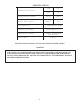
LUBRICATION AND MAINTENANCE CHAR T INTERVAL ACTION PERIODICALLY DURING OPERATION 1. Observe all gauge readings. Note any change from the normal readings and determine the cause. Have necessary repairs made. (NOTE: "NORMAL" is the usual gauge reading when operating at similar conditions on a day to day basis.) DAILY 1. 2. 3. 4. EVERY 25 HOURS OR MONTHLY 1. Drain water from compressor oil. EVERY 500 HOURS OR 6 MONTHS 1. Change compressor oil and replace screen 2.
LUBRICANT RECOMMENDATIONS WARNING IT IS IMPORTANT THAT THE COMPRESSOR OIL BE OF A RECOMMENDED TYPE AND THAT THIS OIL AS WELL AS THE AIR FILTER, OIL FILTER, AND COALESCER ELEMENTS BE INSPECTED AND REPLACED AS STATED IN THIS MANUAL.
LUBRICANT RECOMMENDATIONS LUBRICANT CHARACTERISTICS 1. 2. 3. 4. 5. Flash point 400°F minimum. Pour point -40°F. Contains rust and corrosion inhibitors. Contains foam suppressors. Contains oxidation stabilizer. NOTE DUE TO ENVIRONMENTAL FACTORS THE USEFUL LIFE OFALL “EXTENDED LIFE” LUBRICANTS MAY BE SHORTER THAN QUOTED BYTHE LUBRICANT SUPPLIER. BOSS INDUSTRIES, INC. ENCOURAGES THE USER TO CLOSELY MONITOR THE LUBRICANT CONDITION AND TO PARTICIPATE IN AN OIL ANALYSIS PROGRAM WITH THE SUPPLIER.
MAINTENANCE If some of the maintenance intervals in the schedule outlined in this manual seem to be rather short, it should be considered that one hour’s operation of a compressor is equal to about 40 road miles on an engine. Thus, eight hours operation is equal to 320 road miles, 250 hours is equal to 10,000 road miles, etc. COMPRESSOR OIL SUMP FILL, LEVEL,AND DRAIN Before adding or changing compressor oil make sure that the compressor is completely relieved of pressure.
MAINTENANCE AIR/OIL COALESCER The air/oil coalescer employs an element permanently housed within a spin-on canister . This is a single piece unit that requires replacement when it fails to remove the oil from the discharge air, or pressure drop across it exceeds 15 PSI. Dirty oil clogs the element and increases the pressure drop across it. To replace element proceed as follows: 1. 2. 3. 4. Shutdown compressor and wait for complete blow down (zero pressure).
MAINTENANCE OIL FILTER The compressor oil filter is a throwaway type cartridge. It is designed with a built-in bypass so that if there is a large restriction, due to cold oil or clogged element, the compressor will still be lubricated. To replace filter proceed as follows: 1. Make sure system pressure is relieved. 2. Unscrew with 14mm allen wrench. 3. Remove oil filter from housing. 4. Replace the oil filter screen element. 5. Reinsert oil filter screen into housing and tighten with 14mm allen wrench. 6.
MAINTENANCE SHAFT SEAL SHAFT SEAL INSTALLATION INSTRUCTIONS: 1. Remove hydraulic motor, drive coupling and adapter housing from face of compressor . 2. Remove coupling hub from compressor shaft. 3. Remove 4 screws from shaft seal cover and press seal out. 4. Pull seal wear sleeve off shaft with puller. 5. Clean shaft surface removing all burrs from shaft where the wear sleeve gets installed. 6. Press new wear sleeve on to shaft.
TROUBLESHOOTING This section contains instructions for troubleshooting the equipment following a malfunction. The troubleshooting procedures to be performed on the equipment are listed below . Each symptom of trouble for a component or system is followed by a list of probable causes of the trouble and suggested procedures to be followed to identify the cause.
TROUBLESHOOTING IMPROPER DISCHARGE PRESSURE 1. If discharge pressure is too low, check the following: A. Leaks in service line. B. Restricted compressor inlet air filter. C. Faulty control system operation (i.e.N.0. regulated air solenoid is allowing air through all the time.) D. Low compressor oil level. 2. If discharge pressure is too high, safety valve blows, or system shuts down on high pressure, check the following: A. Faulty discharge pressure switchgauge. B. Coalescer plugged up. C.
TROUBLESHOOTING COALESCER PLUGGING If the coalescer element has to be replaced frequently because it is plugging up, it is an indication that foreign material may be entering the compressor inlet or the compressor oil is breaking down. Compressor oil can break down prematurely for a number or reasons. (1) Extreme operating temperature, (2) negligence in draining condensate from oil sump, (3) using the improper type of oil, (4) dirty oil, (5) oil return nozzle plugged.
COMPRESSOR OPERATION Before starting the compressor, read this section thoroughly. Familiarize yourself with the controls and indicators, their purpose, location, and use. CONTROL OR IN D IC ATOR PURPOSE TEMPERATURE SWITCHGAUGE Monitors the temperature of the air/fluid mixture leaving the compressor. The normal reading should be approximately 175 to 210 degrees F. S ends si gnal to relay when the compressor reaches 240 degrees temperature and the compressor will shut down.
COMPRESSOR OPERATION OPERATING CONDITIONS The following conditions should exist for maximum performance of the compressor . . The truck should be as close to level as possible when operating. The compressor will operate on a 15 degree sideward and lengthwise tilt without any adverse problems. Operation in ambient temperatures above 100°F (38°C) may experience high temperature shutdown. INITIAL START-UP 1. 2. 3. 4. Start power source and allow time for warm-up. Engage hydraulic system.
PARTS AND ILLUSTRATION SECTION 27
28 A B C D 20.00 8 8 7 7 1.00 16.00 4.00 6 6 20.00 5 40.00 48.00 5 4 4 1 REV UPDATED 200470 TO REV 1 DESCRIPTION REVISION HISTORY 3/8-16 UNC - 2B 6-PLACES 3 3 1 200464 3/23/2010 DATE 1 200472 8 CRH ENG 2 Parts List DESCRIPTION 1 THIS DRAWING AND ALL ITS CONTENTS ARE PROPERTY OF BOSS INDUSTRIES, INC. AND MUST NOT BE COPIED OR MADE PUBLIC. IT IS LOANED AND IS SUBJECT TO RETURN UPON DEMAND.
29 A B C D 4 4 2 5 3 1 9 6 3 3 7 4 3 8 THIS DRAWING AND ALL ITS CONTENTS ARE PROPERTY OF BOSS INDUSTRIES, INC. AND MUST NOT BE COPIED OR MADE PUBLIC. IT IS LOANED AND IS SUBJECT TO RETURN UPON DEMAND. THE INFORMATION CONTAINED IN THIS DRAWING IS CONFIDENTIAL AND MUST NOT BE USED, DIRECTLY OR INDIRECTLY, IN ANY WAY DETRIMENTAL TO THE INTEREST OF BOSS INDUSTRIES, INC. 2 Parts List DESCRIPTION 1 10.001 & OVER `.025 5.001 TO 10.000 `.020 1.001 TO 5.000 ` .015 0.000 TO 1.000 ` .
31 308276 A B C D 4 4 14 11 13 9 15 1 12 3 2 10 3 8 QTY 1 1 1 4 8 4 1 1 1 1 1 1 1 1 1 ITEM 1 2 3 4 5 6 7 8 9 10 11 12 13 14 15 4 5 PROPRIETARY INFORMATION 2 Parts List DESCRIPTION 1 10.001 & OVER `.025 5.001 TO 10.000 `.020 1.001 TO 5.000 ` .015 0.000 TO 1.000 ` .010 MACHINED SURFACES NOMINAL DIM. 7 DO NOT SCALE TOLERANCES UNLESS NOTED ANGULAR ` 1° DECIMAL ` .
31 A B C D 8 8 18 7 6 7 12 1 13 10 23 4 14 3 6 6 5 2 9 19 8 8 2 2 2 5 6 7 8 20 1 1 1 1 1 2 3 4 30 17 QTY ITEM 5 31 16 5 14 5 11 33 938810-220 929806-150 970608-050 970802-012 301665 302101 302103 302455 PART NUMBER 24 8 19 7 DESCRIPTION 4 7 25 26 32 4 29 22 21 15 27 28 MOTOR, 1.
32 A B C D 4 7 4 2 3 4 6 10 5 3 11 3 8 9 1 8 8 1 1 4 1 1 1 1 1 1 2 3 4 5 6 7 8 9 10 11 1 QTY ITEM 2 THIS DRAWING AND ALL ITS CONTENTS ARE PROPERTY OF BOSS INDUSTRIES, INC. AND MUST NOT BE COPIED OR MADE PUBLIC. IT IS LOANED AND IS SUBJECT TO RETURN UPON DEMAND. THE INFORMATION CONTAINED IN THIS DRAWING IS CONFIDENTIAL AND MUST NOT BE USED, DIRECTLY OR INDIRECTLY, IN ANY WAY DETRIMENTAL TO THE INTEREST OF BOSS INDUSTRIES, INC. 2 Parts List DESCRIPTION 1 10.001 & OVER `.025 5.
33 A B C D QTY 4 4 28 28 28 6 12 1 7 1 1 1 ITEM 1 2 3 4 5 6 7 8 9 10 11 12 4 23 9 8 12 306891 962008-050 19 PART NUMBER 924301-156 931601-050 938604-071 938004-062 929104-075 943104-038 961504-090 302613 943103-025 306943 4 DESCRIPTION 3 14 11 13 9 17 10 7 21 15 24 3 20 NUT, NYLOC GR5 #8-32 SCREW, MACH RD HD #8-32 X 1/2 WASHER, FLAT GR5 1/4 WASHER, LOC GR5 1/4 BOLT, HEX GR5 1/4-20 X 3/4 RIVET, POP 1/4 X 3/8 ALUMINUM NUT, TINNERMAN 1/4-20 CLIP, 1/2" HYD HOSE HOLDER RIVET, P
34 A B C D 1 1 1 1 1 1 1 1 1 2 3 4 5 NS NS NS 5 1 QTY ITEM PART NUMBER 4 2 302445 300913 305761 300042 305252 301593 301594 300048 4 4 DESCRIPTION 3 1 REV 1 3 REMOVED (1) 302443 & 302444; ADDED (1) 305252 DESCRIPTION REVISION HISTORY DECAL, AIR LEXAN DECAL, OIL DRAIN DECAL, SERIAL TAG BOSS DECAL, WARNING CONNECT AIR DECAL, VALVE BLOCK 80061-12 DECAL, TEMP HYD 140 F30 DECAL, TEMP COMPR 250 F DECAL, DIRECTION OF ROTATION Parts List DATE 3/23/2010 CRH ENG 3 2 THIS DRAWING AND ALL
35 A B C D 4 4 9 5 8 7 1 4 3 3 2 2 3 1 307937 1 960602-012 1 300075 1 301422 6 7 8 9 6 THIS DRAWING AND ALL ITS CONTENTS ARE PROPERTY OF BOSS INDUSTRIES, INC. AND MUST NOT BE COPIED OR MADE PUBLIC. IT IS LOANED AND IS SUBJECT TO RETURN UPON DEMAND. THE INFORMATION CONTAINED IN THIS DRAWING IS CONFIDENTIAL AND MUST NOT BE USED, DIRECTLY OR INDIRECTLY, IN ANY WAY DETRIMENTAL TO THE INTEREST OF BOSS INDUSTRIES, INC. 2 Parts List DESCRIPTION 1 10.001 & OVER `.025 5.001 TO 10.000 `.
+ - ON-OFF for HYDR.System 37 To ener. Hydr.
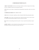
38 308276 #20 SAE "T" TANK OUT PORT #16 SAE "P" PRESSURE IN PORT 4-PIN WIRE HARNESS CONNECTOR M10097 FABCO HYD CONNECTION 1/2" FNPT AIR OUTLET
RECOMMENDED SPARE PARTS PART N UM BER D ESCR IPTION 302601 ELEMEN T, O IL FILTER SCI8 307152 ELEMEN T, AIR FILTER SCI7/8 302600 CO ALESCER, SPIN - O N SCI8/N K 40 307092 K IT, SHAFT SEAL REPAIR SCI8G 302103 SPIDER CO UPLIN G (CO MPRESSO R) 302936 K IT, HYD MO TO R SHAFT SEAL REPAIR 40
Instructional Procedures for Installation of the EAGLE 6 in 1 machine. This unit should be installed only by those who have been trained and delegated to do so and who have read and understand both the operators’ manual and the installation manual. Failure to follow the instructions, procedures, and safety precautions in this manual may result in accidents and injuries. Install, use, and operate this unit only in full compliance with all pertinent O.S.H.A.
INSTRUCTIONAL PROCEDURES 2. INSTALLING THE WIRING & CONNECTING THE HYDRAULIC HOSES This unit is shipped from the factory with all necessary internal wiring installed. The only remaining wiring necessary is the wiring needed to interface your power source with the BOSS INDUSTRIES unit. 1. Connect red wire to battery 12VDC power. 2. The yellow wire should by spliced into 12VDC switched feed for the on/off switch per the end-users location. 3. Connect black wire to ground. 4.
INSTRUCTIONAL PROCEDURES 3. PRE-START-UP INSPECTION CHECKS This inspection should be done prior to removing truck from bay. Final testing of the system, including checking for leaks, is to be done outside. ALL TRUCKS SHOULD BE ROAD TESTED PRIOR TO STARTING INSTALLATION TO ISOLATE ANY PREVIOUS TRUCK PROBLEMS. I. Check sales order to verify that all compressor related items originally ordered have been installed or are ready to ship with the truck.
INSTRUCTIONAL PROCEDURES C. Engage hydraulic system. Flip switch to “compressor activation” switch. Let the compressor run for several minutes to allow compressor to warm up. Flip “welder-generator activation” switch for welder/generator use. CAUTION DO NOT RUN THE COMPRESSOR IN A REVERSE ROTATION FOR PERIODS LONGER THAN 5 SECONDS. CONTINUED OPERA TION IN THIS MANNER WILL RESULT IN EXTENSIVE COMPRESSOR UNIT DAMAGE.
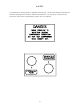
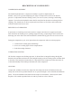
50 125 AC Generator 50 JS125 BC 125 200 145 70 JS 155 85 170 105 135 60 125 50 Min - 200 120 + Welding 24 36 VDC CV 12 VDC + C 24 - 24 VDC + For WELDING Connect Welding Leads to Pos and Neg Welding Terminals Set Range Switch to desired Welding Range Set rotary Switch to desired Amperage With the Min 10 Switch you can lower the Amperage 10 Amps For Battery Charging 12 VDC Connect Battery Cables to lower left and lower right Terminals Set Range Switch to Center ( BC )Position Connect Cables to
50 125 AC Generator BC 125 200 50 JS125 145 70 JS 155 85 170 105 135 60 125 50 200 120 Min 10 - + Welding 24 36 VDC CV 12 VDC + C 24 - 24 VDC + For Jumpstarting 12 V Batteries Connect Cables to lower left and right Terminals Set Range Switch to left or right Position ( right is higher charging ) Set Rotary Switch to highest Position crank Engine For Jumpstarting 24 V Batteries Connect Cables to lower right and Center Terminals Repeat above Switch Settings For wire Feeders Connect Wire feede
General Operating Instructions This hydraulically-driven welder-generator consists of 3 main components : a) hydraulic drive b) DC welder c) AC generator For the welder or generator to function properly the hydraulic drive must maintain the proper speed (3600 – 3720 for 60 Hz,3000-3120 for 50 Hz) under all conditions. Always allow the set to run for at least 2 minutes before operating the welder or generator. Operation 1) Connect welder leads (observe polarity).
FABCO Welders with Jumpstart Option To use the Fabco Welders Jumpstart Option proceed as follows For 12 Volt Jumpstarting a) Set all switches to lowest position,except Range put in High b) Connect Positive Cable to Terminal marked 12 Volt on Welder,connect other end of Cable to Positive on Battery c) Connect Negative Cable to Negative Weld Terminal on Welder Connect other End to the Negative Terminal of Battery d) Start Welder , allow Battery to be charged for 1 to 2 minuts,Crank Engine e) Remove Cabels aft
.. .. .. .. FABCO POWER 1570 Kings Hwy Chester, New York 10918 (845) 469-9151 (Phone) (845) 469-7871 (Fax) Hydro – Arc General Installation The Hydro-Arc is a hydraulically-driven AC welder/generator that will deliver rated amperage when the proper flow is delivered to it’s hydraulic drive. Oil temperature should be between 100-140˚F. A 10-micron filter is also recommended to maintain the drive at its maximum performance.
Important Hydraulic Circuit Installation Information If the hydraulically-driven EAGLE System is mounted below the system tank, it is highly recommended that a check valve with a very low cracking pressure is installed in the case drain line (free flow motor to tank, blocking tank to motor). This will eliminate seal leakage during non-use time. It is also recommended that the case drain be connected directly to the top of the tank and not through a cooler or filter.
Hydro-600 General Installation The Hydro-600 is a hydraulically-driven AC generator that will deliver its rated output power when the proper flow at 2000 PSI is connected to its hydraulic drive. Oil temperature should be between 100-140° F. A 10 micron filter is also recommended to maintain the drive at its maximum performance. Depending on the size of the reservoir, an oil cooler must be used; the smaller the reservoir, the larger the cooler. The tank should NEVER be smaller than 2 times the required GPM.
52 41a 17 13 41d 14 41 22 16 41e 15 21 10a 9a 23 24 39 26 7b 6 27 46 8a a 8 5 5b 47 28 2 3b 4a 44 6 45 43 200 - 225 -250 - 300 DC Welder Parts Illustr.
DC Welder Parts List Page 1 of 2 Item # # Part # 2 3b 4a 5b 6 7b 8a 9a 10a 11 12 13 14b 15 16 17 21 22 23 24a 26b 27 28 29 39 600933 600934 600935 600936 600937 600938 600939 600940 600941 600942 600943 600944 600945 600946 600947 600958 600949 600950 600951 600952 600953 600954 600955 600956 600674 Description Price Front Grid Front Shield B3/B14 Fan Rotor (225-250 Amp) Bearing 225 DC Weld Impedance Black top cover 7 posit. Step Switch (200-225 DC) Range selector (2 pos.
DC Welder Parts List Page 2 of 2 Item # # Part # 40 41 41a 41b 41c 41d 41e 42 43 44 45 46 47 600957 600964 600965 600966 600967 600968 600969 600970 600971 600114 600922 600972 600854 Description Air Intake Recept.Panel Compl. Twistlock Recept Fine Control Ac Light D.Recept. Harness Motor Mount Coupling Set 99 Coupling Guard Flow Reg CC Hyd. Motor U 19 Weld Recept. w.
2FP CC Drive 55 Return Line Drain Case Pressure Line In Speed Adjustment Direct to Tank GETEC Hydraulic
White 120V 60Hz 240V 60Hz Brown & Black Brown Black + 50y 250 Adc Welding Bridge Black Black Blue 6 White White White 4 5 7 AC AC AC 56 Black AC Black - Thermic Probe Fitted Inside The Winding Red + Black Exciting Bridge Red + Rotor AC AC Auxiliary Winding Brown Orange GETEC 250 Amp Range Selector 1 2 3 350 Amp Red Welding Impedance Welding Current Selector Violet Blue Alternator Winding Blue White Blue Brown White Slip Ring Welding Winding Thermic Probe Fitted
2FP95 Hi-Flow Flow Regulator The 2FP95 hi-flow regulator has been factory set to maintain the generator’s speed at its proper limits. The regulator may need very slight adjustments after connecting to its new system. Type of oil, temperatures, minimum and maximum flow may affect this regulator in a different way than our test setup. The regulator will not be out of adjustment more than 1/8 of a turn. Clockwise will slow the generator down (reduce flow).
In 0 Motor 58 Caution Do not allow generator to exceed 3800 RPM Generator 0 Out Case Drain (Viewed From Above) 0 HM 401 AND HW 301 HM 621 AND HW 251 Hydraulic Drive
FABCO 59
White Cut White Blue White Brown Black 120 / 240 Blue Blue 60 0Blue 120 Black White White Brown Black Standard E Panels
WARRANTY SECTION 61
WARRANTY INFORMATION FABCO warrants that this Rotary Screw Compressor unit conforms to applicable drawings and specifications approved in writing by FABCO. The unit assembly will be free from defects in material and workmanship for a period of two (2) years from the date of initial operation or thirty (30) months from the date of shipment, whichever period first expires. All .
SUMMARY OF MAIN WARRANTY PROVISIONS As claims, policies and procedure are governed by the terms of the FABCO warranty is necessary to outline some of the more important provisions. The FABCO warranty applies only to new and unused products which, after shipment from the factory have not been altered, changed, repaired or mistreated in any manner what so ever . . Normal maintenance items such as lubricants and filters are not warrantable items.
WARRANTY/RETURN GOODS INSTRUCTIONS The warranty/return procedure outlined below is provided to give the claimant the information necessary to file a warranty/return claim, and enable FABCO the ability to best serve its’ customers. Please see the following instructions to initiate a return: WARRANTY CLAIMS – PREPARATION OF PART RETURN Parts returned to the factory must be properly packaged to prevent damage during shipment.
GENERAL An approved claim depends on the following provision: 1. An RGA # must be issued by FABCO (See filing procedures.) 2. Failed part must be returned within 30 days of original invoice date, freight prepaid, with RGA #. 3. Part is determined to be defective. 4. Workmanship is determined to be defective. 5. Machine is within warranty period. 6. Machine has been operated within design conditions. DAMAGE IN TRANSIT Do not return damaged merchandise to FABCO, please follow claim procedure. 1.
Terminals 0 1 4 2 5 Heavy Cable connections 66