TFT LCD Widescreen Television Instruction Manual TF TV 3227 Please read this manual carefully before connection and use
Precautions The lightning flash with arrowhead symbol within an equilateral triangle is intended to alert the user to the presence of uninsulated “dangerous voltage” within the product’s enclosure that may be of sufficient magnitude to constitute a risk of electric shock. The exclamation point within an equilateral triangle is intended to alert the user to the presence of important operation and servicing instructions in the literature accompanying the appliance.
Precautions WARNING: To prevent fire or shock hazard, do not expose this device to rain or moisture. Dangerous high voltage is present inside the enclosure. Do not open the cabinet. Note: If the product suddenly has no response or powers off, an electrostatic discharge may be the cause. In this circumstance, please follow the procedures below for recovery: • Unplug the unit. Wait 30 seconds. • After 30 seconds, plug the unit in and turn it on again.
Important Safety Instructions Warnings and precautions To prevent any injuries, the following safety precautions should be observed in the installation, use, servicing and maintenance of this equipment. Before operating this equipment, please read this manual completely, and keep it nearby for future reference. Important Safety Instructions 111 Read these instructions:All the safety and operating instructions should be read before the product is operated.
Important Safety Instructions 2222 Opening and removing the covers may expose you to dangerous voltage or other hazards and may void your warranty. Refer service to qualified personnel. 2222 Do not place or drop any other objects on top.
Important Safety Instructions Antenna Safety Instructions If an outdoor antenna is connected, follow the precautions below: •• •• An outdoor antenna should not be located in any area where it could come in contact with overhead power lines, or any other electric light or power circuits. When installing an outdoor antenna system, extreme caution should be taken to prevent contact with power lines. Direct contact with power lines may be fatal and should be avoided at all costs.
Table of Contents Table Of Contents Precautions Important Safety Instructions Main Feature-----------------------------------------------------------------------------------------------------------------------------1 Package Contents-----------------------------------------------------------------------------------------------------------------2 Unit View---------------------------------------------------------------------------------------------------------------------3 Wall Mounting-----------------------
Main Features Multiple Mode TV AV COMPONENT VGA HDMI 1 HDMI 2 HDMI 3 High Quality Property High Resolution Adopt an MPEG2 decoding format to achieve horizontal resolution more than 500 lines. Superior sound Built-in Dolby Digital decoder to output high quality sound effects.
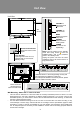
Package Contents Please make sure the following items are included with your product. If any item is missing, contact your dealer. a. b. c.
Unit View Unit View VOLUME +/Adjust the sound output level. TFT Screen CHANNEL +/Skip channels. MENU Display the system setup menu. SOURCE Select a desired working mode. Unit Stand POWER Turn the unit on/ off(standby). Remote Control Senser Sense the remote control signal. NOTE: The unit enters into the standby mode after being turned off with the POWER button, and it still consumes power in the standby mode.
Remote Control Remote Control Drawing 1. POWER Press this button to turn the unit on/off (standby). 2. Numeric Keypad Press these buttons to input numberic data as well as to access a TV channel directly. 3. Sub-channel Selector <-> This button is usually used with the numeric keypad to tune to a channel substation (e.g., 4-1, 4-2). 4. VOLUME +/These two buttons are used to adjust the volume up or down. 5. CH/LIST Press this button to display the program list. 6.
Remote Control Remote Control Preparation •• Remove the battery compartment cover located on the rear of the remote control. Insert 2 x “AAA” batteries, making sure to match their polarities (+/-) to the markings on the inside of the compartment. Replace the cover. •• Batteries in the remote will last for approximately 6 months under the normal use. Replace the batteries if the remote control does not work. Do not mix old with new batteries, or different types of batteries.
Cable Connections Figure. Cable connections Power Connection Insert the power plug into the 110-240V AC wall outlet. If you have difficulty inserting the plug, turn it over and re-insert it. IMPORTANT NOTICE 111 Be sure to have all necessary connections properly done before connect the power supply. 222 If the product will not be used for a long period of time, disconnect the power. Antenna Connection Connect TV RF sources to the antenna port. TV RF signals include: receiving antenna/CATV net.
Cable Connections VGA Input - PC Connection The VGA port of the TV is capable of accepting high-definition signals from computers with a VGA output jack. When used as a computer moniter, connect the VGA jack and the PC Audio In jack with a 15-Pin D-Sub cable and a 3.5mm stereo audio cable. The mentioned cables are not included with this product.
Cable Connections COAXIAL (S/PDIF) - General Information This port is usually found on digital audio equipment such as a DAT (Digital Audio Tape) machine or audio processing device. It allows the transfer of audio from one file to another without the conversion to and from an analog format, which could degrade the signal quality. The most common connector used with an S/PDIF interface is the RCA connector, the same one used for consumer audio products. An optical connector is also sometimes used.
Cable Connections HDMI 1/2/3 Input HDMI (High Definition Multimedia Interface) is a new type of connection that transmits digital audio and video signals simultaneously over a single cable. A HDMI cable is required for the HDMI connection. These HDMI input connectors are capable of receiving video at resolutions up to 1080p (1080-progressive). HDMI 1/2 is used in the same application as HDMI 3 illustrated in the below picture.
Cable Connections Component Input (Y Cb/Pb Cr/Pr) The component port is capable of accepting high-definition signals from standard video sources. (e.g., cable/ satellite boxes, DVD players, VCRs, etc.) 111 Connect the Y, Pb, Pr port by the component cable to input the video signal. Component cabel is not included with this product. 222 Use the red/white plug of supplied AV cable to connect R,L port for audio transmission.
TV Function Preparations 111 222 333 444 . Connect cables.(Refer to the “Cable Connections” section for details). Press the POWER button to turn on the player. Select the TV signal mode, using the SOURCE button. Press CH+/- to skip channels. Or you can use number buttons to access a channel directly. For an initial use, you need to scan channels under the Channesl Menu, please follow steps below. Press the MENU button to display system menu window, use direction buttons to access the CHANNELS menu.
TV Function Audio Menu ITEM DESCRIPTION Mode Treble/Bass/Balance Digital Audio/SPDIF (COAXIAL) MTS/SAP Audio Language Reset Audio Settings Set the audio mode as Custom/Standard/Theater/ Music/News. Press the left/right direction button to adjust settings.
TV Function Settings Menu ITEM DESCRIPTION Parental Controls You are required to enter the 4-digit password to access this Button Lock - This option would enable users to lock buttons on the unit panel. Block Unrated TV -This option would enable users to lock unrated TV program. USA Parental Locks - Setup the US parental control.
TV Function Settings Menu ITEM DESCRIPTION Time This option would enable users to adjust Date/Time information as well as to setup the sleep timer. Date/Time - Enter this option, set "Mode" as "Auto" / "Custom". When Mode is set as "Auto", system would adjust date/time information automatically after you select a desired Time Zone.
AV Function The player’s AV input function would enable user to view programs from external signal sources. When input AV signals, read the user's manual of the external device as well. 111 Connect the external AV signal source. Refer to the “Cable Connection” section for details 222 Use the SOURCE button to select the relevant AV mode (AV, S-Video, Component, HDMI). System Setup Menu Various features can be preset through the setup menu, please read this section carefully.
PC Function The unit’s screen can be used as your computer’s monitor. 111 Shut down PC and this unit, connect the VGA jack and PC Audio In jack with a 15 -Pin D-Sub cable and a 3.5mm stereo audio cable. See the “Cable Connection” section for details. 222 Turn on both units and use the SOURCE button to select VGA Important Notice •• There may be interference relating to resolution, vertical pattern, contrast or brightness in PC mode.
Trouble Shooting If you have a problem with this device, please read the troubleshooting guide section and check our website at www.cobyusa.com for Frequently Asked Questions (FAQs) and firmware updates. If these resources do not resolve the problem, please contact Technical Support. COBY Electronics Technical Support 150 Knowlton Way Savannah, GA 31407 Email : techsupport@cobyusa.com Web : www.cobyusa.
Specification TF TV 3227 TFT Panel Characteristic TV Charactoristic Active Area 32" Resolution 1366XRGBX768 Display Color 16.7M colors Pixel Pitch 0.51075(V) X0.51075(H) TV System ATSC/NTSC Antenna Impedance 75Ω Standby Power Consumption <1W Power Consumption AC100-240V 50/60Hz Standard On Working 130W(Max) Speaker 2x(8Ω, 10W) Operating Temperature Range 0ºc-40ºc Wall Mounting 200X200MM, VESA M6.