Small Cell Radio Node - SCRN-510 Hardware Installation Guide DOC-SCRN-510-HIG_i4 Issue 4 Related Literature | Search www.Corning.com/opcomm. Click Required Resources.
FCC Statement Caution: Any changes or modifications to this device not explicitly approved by manufacturer could void your authority to operate this equipment. RF Exposure warning statement: This equipment complies with FCC radiation exposure limits set forth for an uncontrolled environment. This equipment should be installed and operated with minimum 40 cm between the radiator and your body.
NOTE: This device does not require professional installation. Other Cautions CAUTION: ESD can damage the SCRN-510 and internal components. Ensure that the SCRN-510 and associated antenna equipment is installed and serviced according to national and local ESD standards. CAUTION: Ensure that the antenna cable conforms to the environment in which it is used. CAUTION: Do not open the SCRN-510 casing. E-RAN wireless system equipment must only be serviced by Corning-accredited personnel.
Table of Contents FCC Statement . . . . . . . . . . . . . . . . . . . . . . . . . . . . . . . . . . . . . . . . . . . . . . . . . . . . . . . 2 Safety Precautions . . . . . . . . . . . . . . . . . . . . . . . . . . . . . . . . . . . . . . . . . . . . . . . . . . . . 2 Other Cautions . . . . . . . . . . . . . . . . . . . . . . . . . . . . . . . . . . . . . . . . . . . . . . . . . . . . . . . 3 Section 1. About this Manual . . . . . . . . . . . . . . . . . . . . . . . . . . . . . . . . . . . . . . . . . .
1. About this Manual The Corning SCRN-510 small cell radio node is an integrated 5G new radio (NR) mmWave radio node that is part of the Corning enterprise radio access network (E-RAN). The scalable SCRN-510 radio node and the enterprise radio access network (E-RAN) simplify the complexity of radio management and mobility, and provide operators with a single interface to aggregate and manage a large network of radio nodes. This guide provides the system specifications of the SCRN-510.
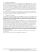
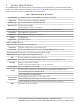
4G and 5G EN-DC RAN SCRN-510 Radio Nodes NR (5G) DC Power PSU6 10G Connections 5G RN Fronthaul 5G Centralized Unit (CU) Core Switch 5G EN-DC UEs CU IPsec Backhaul S1-U 3GPP GTP Tunnel DMZ Security Gateway X2 4G Services Node (SCSN) 4G RN Fronthaul Mobile Operator Core Firewall SCSN IPsec Backhaul 3GPP Tunnel PoE+ Switch LTE (4G) Email Web 1G Connections 4G Radio Nodes 4G UEs Enterprise Figure 1 3.
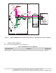
3.1 Radio Node Cover-Side and Mounting-Side Views Figure 2 and Figure 3 display cover and mounting-side views of the radio node.
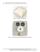
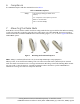
4. Connectors, SFP+ and Micro-USB Ports, and Status LED The radio node has the following connectors and a small form-factor pluggable SFP+ port, as shown in Figure 4. 4.1 Duplex Phoenix Power Cable Ports The SCRN-510 has two 48 VDC power connectors for delivering power from a Corning PSU6 DC Power Supply Unit or equivalent to the radio node.
5. System Specifications The SCRN-510 radio node has the chassis measurements, power requirements, and environmental requirements, and complies with the standards listed in Table 2. Refer to the feature guide for your centralized unit software release for release-specific features and specifications. Table 2 SCRN-510 Radio Node Specifications Operating Band 2 x 2 MIMO operation on 28-GHz NR band n261 (27.5–28.
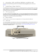
6. Compliance The SCRN-510 complies with the standards listed in Table 3. Table 3 SCRN-510 Compliance Safety TUV Safety (Including UL-62368-1 2nd Edition) FCC Compliant - Part 15 (Class A), Part 30 MPE: FCC 47 CFR 1.1310 UR: FCC 47 CFR 1.1307(b) 7. Mounting the Radio Node Radio Nodes can be installed on walls and below ceilings with the factory-provided brackets. When mounting a radio node vertically on a wall, position the fans on the upper side of the SCRN-510.
7.1 Flush Mounting the SCRN-510 As shown in Figure 3, the SCRN-510 comes with the ceiling-mount bracket attached. This bracket is held to the radio node mounting side with four shoulder screws and a captive securing screw, and is non-tilting. The shoulder screws should not need to be adjusted but if they do, loosen them slightly to be able to slide the ceiling-mount bracket on and off of the radio node when the captive securing screw has been loosened.
Figure 7 7.2 Ceiling-Mounted SCRN-510 Downtilt Mounting the SCRN-510 The SCRN-510 comes with the ceiling-mount bracket attached, and has the multi-angle wall-mount bracket loose in the box. Figure 8 shows the SCRN-510 wall-mount bracket.
Figure 9 Wall-Mount Bracket Attached to the Ceiling-Mount Bracket Step 1 Using a spirit level, use the wall-mount bracket as a template to mark securing hole locations. Step 2 If required, install sheet rock plugs. Step 3 Attach the wall-mount bracket to the wall. Figure 10 shows the SCRN-510 wall-mount bracket attached to a wall. Figure 10 Wall-Mount Bracket Attached to a Wall NOTE: Production wall-mount brackets will have a large hole in the back for routing cables.
Figure 11 shows how to attach the wall-mount bracket to the ceiling-mount bracket. 1 Figure 11 2 Attaching the Wall-Mount Bracket to the Ceiling-Mount Bracket Step 5 Make sure that both of the captive securing screws are tightened. 8. Cabling Guidelines Incorrectly cabling a SCRN-510 can result in crushed cables and loss of communications to the radio node. Follow these guidelines when cabling the radio node: 9. • Make sure that the cabling is properly routed and dressed.
tions. On failure, the last LED state will display the state that encountered the failure. Table 4 shows the radio node boot sequence and corresponding LED behavior. Table 4 Radio Node LED Boot Sequence State LED Color Description Possible Failures and Actions 0. Power On/ Reset Flashing White This is the initial state on startup. The radio This state should be very short lived node bootup is controlled by firmware in this and should transition to the next state state. immediately. 1.
12. Radio Node LED Management The LED display is active by default, but can be deactivated in light-sensitive environments as needed.
13. Corning Documentation Set The Corning documentation can be downloaded from the customer support portal (the “Corning One Community”) at https://onesupport.corning.com. This site requires a login which is available to individuals who have attended Corning Small Cell training in the past two years. Email onesupport@corning.com to request a login if you meet these criteria.