
Installation Guide
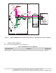
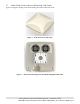
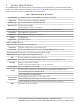
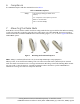
Table Of Contents
- 1. About this Manual
- 2. Product Overview
- 3. Radio Node Model
- 4. Connectors, SFP+ and Micro-USB Ports, and Status LED
- 5. System Specifications
- 6. Compliance
- 7. Mounting the Radio Node
- Always consult and follow local codes for mounting and wiring Corning equipment.
- 7.1 Flush Mounting the SCRN-510
- The security screws should not need to be adjusted but if they do, loosen them slightly to be able to slide the ceiling-mount bracket on and off.
- The shoulder screws should not need to be adjusted but if they do, loosen them slightly to be able to slide the ceiling-mount bracket on and off.
- Corning recommends that you use a customer-supplied projector mount when hanging the SCRN-510 from a dropped T-bar ceiling.
- 7.2 Downtilt Mounting the SCRN-510
- 8. Cabling Guidelines
- 9. Completing the Installation
- 10. Detaching the Radio Node from the Mounting Brackets
- 11. Radio Node LED Boot Sequence
- 12. Radio Node LED Management
- 13. Corning Documentation Set

Corning Restricted and Confidential Proprietary - Controlled content
SCRN-510 Hardware Installation Guide | DOC-SCRN-510-HIG_i4 | 16 October, 2020 | Page 10
6. Compliance
The SCRN-510 complies with the standards listed in Table 3.
7. Mounting the Radio Node
Radio Nodes can be installed on walls and below ceilings with the factory-provided brackets. When mounting
a radio node vertically on a wall, position the fans on the upper side of the SCRN-510. The factory-provided
wall-mount bracket can tilt the SCRN-510 down at the following angles:
0°, 15°, 30° and 45°. Figure 5 shows the
SCRN-510 tilt options.
Figure 5 Mounting Bracket Downtilt Options
NOTE: Always consult and follow local codes for mounting and wiring Corning equipment.
When possible, locate downward-radiating radio node units at least 0.5 meters (20 inches) from external
walls. This distance maximizes indoor coverage and minimizes RF leakage outside the building. When mount-
ing near a wall or other obstruction, orient the mounting bracket so that the top of the SCRN-510 faces
towards the coverage area and faces away from the wall.
Table 3 SCRN-510 Compliance
Safety
TUV Safety (Including UL-62368-1 2nd
Edition)
FCC Compliant - Part 15 (Class A), Part 30
MPE: FCC 47 CFR 1.1310
UR: FCC 47 CFR 1.1307(b)
0° 15° 30° 45°