
Installation Guide
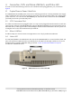
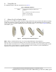
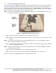
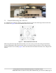
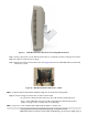
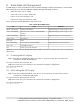
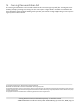
Table Of Contents
- 1. About this Manual
- 2. Product Overview
- 3. Radio Node Model
- 4. Connectors, SFP+ and Micro-USB Ports, and Status LED
- 5. System Specifications
- 6. Compliance
- 7. Mounting the Radio Node
- Always consult and follow local codes for mounting and wiring Corning equipment.
- 7.1 Flush Mounting the SCRN-510
- The security screws should not need to be adjusted but if they do, loosen them slightly to be able to slide the ceiling-mount bracket on and off.
- The shoulder screws should not need to be adjusted but if they do, loosen them slightly to be able to slide the ceiling-mount bracket on and off.
- Corning recommends that you use a customer-supplied projector mount when hanging the SCRN-510 from a dropped T-bar ceiling.
- 7.2 Downtilt Mounting the SCRN-510
- 8. Cabling Guidelines
- 9. Completing the Installation
- 10. Detaching the Radio Node from the Mounting Brackets
- 11. Radio Node LED Boot Sequence
- 12. Radio Node LED Management
- 13. Corning Documentation Set

Corning Restricted and Confidential Proprietary - Controlled content
SCRN-510 Hardware Installation Guide | DOC-SCRN-510-HIG_i4 | 16 October, 2020 | Page 13
Figure 9 Wall-Mount Bracket Attached to the Ceiling-Mount Bracket
Step 1 Using a spirit level, use the wall-mount bracket as a template to mark securing hole locations.
Step 2 If required, install sheet rock plugs.
Step 3 Attach the wall-mount bracket to the wall. Figure 10 shows the SCRN-510 wall-mount bracket
attached to a wall.
Figure 10 Wall-Mount Bracket Attached to a Wall
NOTE: Production wall-mount brackets will have a large hole in the back for routing cables.
Step 4 Seat the ceiling-mount bracket on wall-mount bracket:
- First, slide the ceiling-mount bracket onto the wall-mount bracket hinge pins.
- Then, set the SCRN-510 to the required tilt, and tighten the wall-mount bracket
captive securing screw to lock the radio node tilt angle.
NOTE: Put pressure on the SCRN-510 when tightening the captive securing screw.