
Installation Guide
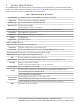
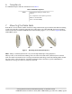
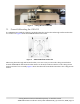
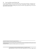
Table Of Contents
- 1. About this Manual
- 2. Product Overview
- 3. Radio Node Model
- 4. Connectors, SFP+ and Micro-USB Ports, and Status LED
- 5. System Specifications
- 6. Compliance
- 7. Mounting the Radio Node
- Always consult and follow local codes for mounting and wiring Corning equipment.
- 7.1 Flush Mounting the SCRN-510
- The security screws should not need to be adjusted but if they do, loosen them slightly to be able to slide the ceiling-mount bracket on and off.
- The shoulder screws should not need to be adjusted but if they do, loosen them slightly to be able to slide the ceiling-mount bracket on and off.
- Corning recommends that you use a customer-supplied projector mount when hanging the SCRN-510 from a dropped T-bar ceiling.
- 7.2 Downtilt Mounting the SCRN-510
- 8. Cabling Guidelines
- 9. Completing the Installation
- 10. Detaching the Radio Node from the Mounting Brackets
- 11. Radio Node LED Boot Sequence
- 12. Radio Node LED Management
- 13. Corning Documentation Set

Corning Restricted and Confidential Proprietary - Controlled content
SCRN-510 Hardware Installation Guide | DOC-SCRN-510-HIG_i4 | 16 October, 2020 | Page 14
Figure 11 shows how to attach the wall-mount bracket to the ceiling-mount bracket.
Figure 11 Attaching the Wall-Mount Bracket to the Ceiling-Mount Bracket
Step 5 Make sure that both of the captive securing screws are tightened.
8. Cabling Guidelines
Incorrectly cabling a SCRN-510 can result in crushed cables and loss of communications to the radio node. Fol-
low these guidelines when cabling the radio node:
• Make sure that the cabling is properly routed and dressed.
• When mounting the radio node vertically, orient the bracket so that the bracket keyholes have the
wide side up as shown in Figure 3.
• Make sure that the radio node is fully secured to the mounting brackets so that it locks into place.
A correctly-installed cable should at no time during installation impede inserting the radio node
into the mounting brackets.
9. Completing the Installation
Step 1 Make sure that the captive securing screws are tightened. The radio node is now anchored.
Step 2 When it receives power, the radio node boots up and attempts to connect to the centralized
unit.
10. Detaching the Radio Node from the Mounting Brackets
Step 1 Loosen the captive securing screws anchoring the radio node to its mounting brackets.
Step 2 Slide the radio node out of the mounting brackets.
Step 3 Detach the cables from the cable brackets and cable openings.
11. Radio Node LED Boot Sequence
The radio node state machine is sequential and progresses in the following order:
State 0 -> State 1 -> State 2 -> State 3 -> State 4 -> State 5 -> State 6
A normal boot sequence transitions through all these states sequentially and the LED state transitions
accordingly. If the radio node fails to transition to the next state, the system restarts the boot sequence, start-
ing with State 0. You can determine the progress during the booting stages by observing the LED color transi-
1
2