
Installation Guide
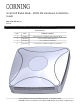
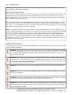
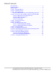
Table Of Contents
- 1. About this Manual
- 2. Product Overview
- 3. Radio Node Model
- 4. Connectors, SFP+ and Micro-USB Ports, and Status LED
- 5. System Specifications
- 6. Compliance
- 7. Mounting the Radio Node
- Always consult and follow local codes for mounting and wiring Corning equipment.
- 7.1 Flush Mounting the SCRN-510
- The security screws should not need to be adjusted but if they do, loosen them slightly to be able to slide the ceiling-mount bracket on and off.
- The shoulder screws should not need to be adjusted but if they do, loosen them slightly to be able to slide the ceiling-mount bracket on and off.
- Corning recommends that you use a customer-supplied projector mount when hanging the SCRN-510 from a dropped T-bar ceiling.
- 7.2 Downtilt Mounting the SCRN-510
- 8. Cabling Guidelines
- 9. Completing the Installation
- 10. Detaching the Radio Node from the Mounting Brackets
- 11. Radio Node LED Boot Sequence
- 12. Radio Node LED Management
- 13. Corning Documentation Set

Corning Restricted and Confidential Proprietary - Controlled content
SCRN-510 Hardware Installation Guide | DOC-SCRN-510-HIG_i4 | 16 October, 2020 | Page 3
Other Cautions
NOTE: This device does not require professional installation.
CAUTION: ESD can damage the SCRN-510 and internal components. Ensure that the SCRN-510 and
associated antenna equipment is installed and serviced according to national and local ESD stan-
dards.
CAUTION: Ensure that the antenna cable conforms to the environment in which it is used.
CAUTION: Do not open the SCRN-510 casing. E-RAN wireless system equipment must only be ser-
viced by Corning-accredited personnel. Opening the SCRN-510 casing voids the warranty.