
Installation Guide
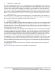
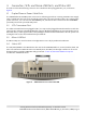
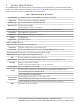
Table Of Contents
- 1. About this Manual
- 2. Product Overview
- 3. Radio Node Model
- 4. Connectors, SFP+ and Micro-USB Ports, and Status LED
- 5. System Specifications
- 6. Compliance
- 7. Mounting the Radio Node
- Always consult and follow local codes for mounting and wiring Corning equipment.
- 7.1 Flush Mounting the SCRN-510
- The security screws should not need to be adjusted but if they do, loosen them slightly to be able to slide the ceiling-mount bracket on and off.
- The shoulder screws should not need to be adjusted but if they do, loosen them slightly to be able to slide the ceiling-mount bracket on and off.
- Corning recommends that you use a customer-supplied projector mount when hanging the SCRN-510 from a dropped T-bar ceiling.
- 7.2 Downtilt Mounting the SCRN-510
- 8. Cabling Guidelines
- 9. Completing the Installation
- 10. Detaching the Radio Node from the Mounting Brackets
- 11. Radio Node LED Boot Sequence
- 12. Radio Node LED Management
- 13. Corning Documentation Set

Corning Restricted and Confidential Proprietary - Controlled content
SCRN-510 Hardware Installation Guide | DOC-SCRN-510-HIG_i4 | 16 October, 2020 | Page 6
Figure 1 5G NR and E-RAN Radio Node Relationship to Enterprise and Mobile Operator Core Networks
3. Radio Node Model
Table 1 includes the SCRN-510 radio node configuration.
Table 1 SCRN-510 Radio Node Configuration
Radio Node Model Description Antenna Type
SCRN-510-28G1 28 GHz band n261 mmWave RN with 8 x 8 dual-polarization antenna array Internal
Email Web
DMZ
Enterprise
Mobile
Operator
Core
SCRN-510
Radio
Nodes
5G RN
Fronthaul
Core
Switch
Firewall
Security
Gateway
5G
EN-DC
UEs
PSU6
5G Centralized
Unit (CU)
NR
(5G)
DC
Power
10G
Connections
4G RN
Fronthaul
PoE+
Switch
4G Services
Node (SCSN)
4G and 5G EN-DC RAN
LTE
(4G)
CU IPsec
Backhaul
S1-U
3GPP
GTP Tunnel
4G
Radio
Nodes
1G
Connections
SCSN IPsec
Backhaul
3GPP
Tunnel
X2
4G
UEs