
Installation Guide
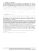
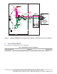
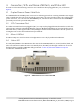
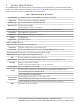
Table Of Contents
- 1. About this Manual
- 2. Product Overview
- 3. Radio Node Model
- 4. Connectors, SFP+ and Micro-USB Ports, and Status LED
- 5. System Specifications
- 6. Compliance
- 7. Mounting the Radio Node
- Always consult and follow local codes for mounting and wiring Corning equipment.
- 7.1 Flush Mounting the SCRN-510
- The security screws should not need to be adjusted but if they do, loosen them slightly to be able to slide the ceiling-mount bracket on and off.
- The shoulder screws should not need to be adjusted but if they do, loosen them slightly to be able to slide the ceiling-mount bracket on and off.
- Corning recommends that you use a customer-supplied projector mount when hanging the SCRN-510 from a dropped T-bar ceiling.
- 7.2 Downtilt Mounting the SCRN-510
- 8. Cabling Guidelines
- 9. Completing the Installation
- 10. Detaching the Radio Node from the Mounting Brackets
- 11. Radio Node LED Boot Sequence
- 12. Radio Node LED Management
- 13. Corning Documentation Set

Corning Restricted and Confidential Proprietary - Controlled content
SCRN-510 Hardware Installation Guide | DOC-SCRN-510-HIG_i4 | 16 October, 2020 | Page 8
4. Connectors, SFP+ and Micro-USB Ports, and Status LED
The radio node has the following connectors and a small form-factor pluggable SFP+ port, as shown in
Figure 4.
4.1 Duplex Phoenix Power Cable Ports
The SCRN-510 has two 48 VDC power connectors for delivering power from a Corning PSU6 DC Power Supply
Unit or equivalent to the radio node. Plug the Phoenix power connectors from the power source cable into the
power connectors; one connector into the PRIMARY port, and then another connector into the SECONDARY
port. Both ports must be provided with power.
4.2 SFP+ Transceiver Port
The enhanced small form-factor pluggable (SFP+) is a compact, hot-pluggable network interface module. The
approved SFP+ included on the Bill Of Materials supports 10 GbE (Gigabit Ethernet). Connect the fiber pair of
the ActiFi cable (or other approved fiber cable) with approved SFP module termination to the SFP port for con-
necting the radio node to the fronthaul transport network.
4.3 Micro-USB Port
The Micro-USB port is used for advanced configuration. For use only by authorized technicians.
4.4 Status LED
The STA (status) RGB tri-color LED indicates the state of the SCRN-510, with boot, normal, disabled, fault, and
radio node indications. When the radio node initially boots, the LED cycles through a number of colors and
flashing behaviors until the SCRN-510 is fully operational. Section 11., Radio Node LED Boot Sequence
describes the STA LED indications.
Figure 4 SCRN-510 Connectors and Status LED