
Installation Guide
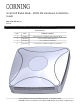
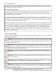
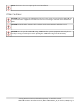
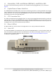
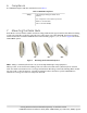
Table Of Contents
- 1. About this Manual
- 2. Product Overview
- 3. Radio Node Model
- 4. Connectors, SFP+ and Micro-USB Ports, and Status LED
- 5. System Specifications
- 6. Compliance
- 7. Mounting the Radio Node
- Always consult and follow local codes for mounting and wiring Corning equipment.
- 7.1 Flush Mounting the SCRN-510
- The security screws should not need to be adjusted but if they do, loosen them slightly to be able to slide the ceiling-mount bracket on and off.
- The shoulder screws should not need to be adjusted but if they do, loosen them slightly to be able to slide the ceiling-mount bracket on and off.
- Corning recommends that you use a customer-supplied projector mount when hanging the SCRN-510 from a dropped T-bar ceiling.
- 7.2 Downtilt Mounting the SCRN-510
- 8. Cabling Guidelines
- 9. Completing the Installation
- 10. Detaching the Radio Node from the Mounting Brackets
- 11. Radio Node LED Boot Sequence
- 12. Radio Node LED Management
- 13. Corning Documentation Set

Corning Restricted and Confidential Proprietary - Controlled content
SCRN-510 Hardware Installation Guide | DOC-SCRN-510-HIG_i4 | 16 October, 2020 | Page 9
5. System Specifications
The SCRN-510 radio node has the chassis measurements, power requirements, and environmental require-
ments, and complies with the standards listed in Table 2. Refer to the feature guide for your centralized unit
software release for release-specific features and specifications.
Table 2 SCRN-510 Radio Node Specifications
Operating Band 2 x 2 MIMO operation on 28-GHz NR band n261 (27.5–28.35 GHz)
Channel Size Component Carrier (CC) bandwidth: 100 MHz
Antenna Type 8 x 8 dual-polarization internal antenna array
Antenna Power
43 dBm EIRP @ 64QAM
Beamforming scan range: +/- 60 degrees
RF Management Beam Management with auto-assignment of physical cell identities (PCIs)
QoS Features Non-GBR bearer support per UE
Dimensions 31.75 x 31.75 x 11.43 mm (12.5 x 12.5 x 4.5 in)
Weight 5.31 kg (11.72 lbs)
Input Power 2 x 48 VDC Phoenix
Power Consumption 100 W
Ingress Protection Ingress protection rating: IP30
Performance Hardware capable of 4CC; up to 32 active users
Peak Tx Rate 1.1 Gbps DL, 60 Mbps UL (DL:UL slot ratio of 4:1) @ 64QAM with 2CC DL, 1CC UL
Licensed Tx Power Equivalent isotropically radiated power (EIRP): 43 dBm
Ethernet Interface SFP+ supports 10 GbE (Gigabit Ethernet)
LEDs 1 tricolor (RGB) LED to indicate power and status
Synchronization IEEE 1588v2-based (PTP) synchronization with an external PTP grandmaster clock
Mounting
Wall or Ceiling, brackets included
Brackets support four tilting options: 0°, 15°, 30° and 45° tilt
Cooling Method Active cooling (Noise level: 30 dBA)
Security
Secure boot and secure key storage using Trusted Platform Module (TPM) functions
IPsec tunneling to NR CU (Centralized Unit)
X.509 certificate-based authentication
Environmental
Requirements
Operating temperature range: 0
o
to 45
o
C (32
o
to 113
o
F)
Non-operating temperature range: -40
o
to +70
o
C (-40
o
to 158
o
F)
Relative humidity: Operating and storage: 0% RH to 90% RH non-condensing
MTBF 1,363,791 hours at +40°C (104°F)