User’s Manual PowerTALK 101 - Ethernet to Serial converter
PowerTALK 101 PowerTALK 101 Configuration, usage and testing guide for PowerTALK 101 communications equipment. Manual release date: 20 October 1998 Manual Release 2 Supersedes manual, release 1, 15 Oct 98 Supersedes preliminary manual, rev 0.3 Supersedes preliminary manual, rev 0.2 Supersedes preliminary manual, rev 0.1 PowerTALK 101 Firmware release 1.00 PT.EXE Configuration software, release 1.
PowerTALK 101 Table of Contents TABLE OF CONTENTS ............................................................................................................................. 3 FOREWORD ................................................................................................................................................ 5 INTRODUCTION ........................................................................................................................................ 7 BRIEF DESCRIPTION .......
PowerTALK 101 Power Supply........................................................................................................................................ 25 Networking ........................................................................................................................................... 25 CHANGING MORE ADVANCED PARAMETERS USING PT.EXE...................................................................... 26 PASSWORDS..............................................................
PowerTALK 101 Foreword The PowerTALK product family, available from www.cocoon-creations.com, is a modular set of tools that enable engineers and process controllers to centralise the monitoring and management of proprietary industrial equipment. COCOON has recognised that there is legacy equipment in production today that is robust, reliable and relatively inexpensive, however, such equipment often comes with limited ability on-board for centralised monitoring and management.
PowerTALK 101 6
PowerTALK 101 Introduction Brief description PowerTALK 101 is an Ethernet-to-Serial Converter that packages serial data into TCP/IP packets that are transmitted through a standard Ethernet port and onto the corporate or industrial network / Intranet / Internet. It simultaneously also does the inverse: TCP/IP packets that are addressed to PowerTALK 101’s IP Address (user definable) is accepted by the device and repackaged into the original stream of serial data and is sent to the appropriate serial port.
PowerTALK 101 Ordering options Default specifications for PowerTALK 101: Power Supply: 230VAC Network Connection: 10-BASE-T Ethernet Serial Connectors: 2 off 9-pin D-type serial connectors, Broadcast mode: UDP The PowerTALK unit is marked at the back with the relevant information, including the standard fixed IP address. See page 14 for Device and terminal identification.
PowerTALK 101 PowerTALK 101 overview Feature overview • PowerTALK 101 can transport any serial protocol over standard Ethernet networks using standardised transmission methods • PowerTALK 101 can be Installed at any point on an Ethernet network • Communication parameters can be changed from any port: local, remote or networked • PowerTALK 101 is delivered with a standard IP to which it always respond. • PowerTALK 101 can be configured with a second IP to fit into your network scheme.
PowerTALK 101 Functional overview of PowerTALK 101 PowerTALK 101 is a network protocol converter, one unit having at least a serial port and an Ethernet port. All PowerTALK 101 models utilise the TCP/IP protocol suite for communication and configuration. PowerTALK 101 uses UDP broadcast packets to effectively combine a campus wide Ethernet network into one virtual RS-232 multi-drop network.
PowerTALK 101 Schematic overview of PowerTALK 101 Ethernet LAN segment, TCP/IP, UDP, etc.
PowerTALK 101 Network topology overview of PowerTALK 101 PC Hub (UTP/ Thinnet) Configuration PC On Ethernet Ethernet PowerTALK 101 RS-232 Serial devices RS-232 Master PC On COM port 12
PowerTALK 101 Physical properties PowerTALK 101 picture Front view Rear view LED, plug and switch layout Reset Serial 1 Serial 2 Ethernet Green: ON Green: Transmit Green: Transmit Green: Transmit Reset Press to restart all on-board processors in case of suspected system malfunction, or LED test Serial Port 1: 1200 – 19200 bps, 5,6,7,8 bits, NOE parity, 1,2 stop bits Serial Port 2: 1200 – 19200 bps, 5,6,7,8 bits, NOE parity, 1,2 stop bits Ethernet medium – 10 Mbps 10-BASE-T Serial 1 Serial 2 Ethernet
PowerTALK 101 Device and terminal identification Typical label for the 230VAC model, mounted on rear of PowerTALK 101: Dimensions PowerTALK 101 maximum dimensions. Above dimensions exclude the terminal rail at the back of the PowerTALK 101 box. Rear DIN rail The 35mm DIN rail is provided for convenience, to mount up to two PowerTALK 103 RS-485 converters or other third party rail mount equipment such as power supplies, etc.
PowerTALK 101 The front surface is of brushed stainless steel, and shows fingerprints easily on the textured finish. To remove, use a cloth with alcohol or spirits. Take care not to allow the volatile fluid to come into contact with the vinyl stickers on the surface of the front plate. When wiping the front panel surface, wipe horizontally; in the same direction as the brush finish texture for the best results.
PowerTALK 101 Fuses & links • One PC board mounted 5mmx20mm fuse, 1A rating, fast blow This fuse is for PSU overload protection • Between terminals X1:2 and X1:6, a fuse with 3A rating, slow blow This fuse is for short circuit protection against possible short circuit inside the box • Between terminals X1:1 and X1:5, a link terminal A link is used to isolate the Neutral or Negative power supply if needed.
PowerTALK 101 Jumper settings PowerTALK 101 contains two printed circuit boards: Power supply board No jumpers or options on board A. One 2-pin, 0.3” spaced connector connected to power input This connection is connected to terminals X1:1,5 and X1:2,6. B. One 2-pin, 0.1” spaced connector with output 12VDC, 50mA This supply is not needed by PowerTALK 101, but can be used by the user’s equipment C. One set of screw terminals for output 5VDC, 4A. N.B.
PowerTALK 101 Communications processor board Jumper settings are not user configurable, and are to be as per diagram below: Connections A. B. C. D. E. F. G. Port 1 to SERIAL 1 (green CAT-5 UTP cable) to front plate connector Port 2 to SERIAL 2 (blue CAT-5 UTP cable) to front plate connector RJ-45 to ETHERNET (yellow CAT-5 UTP cable) on front plate 2-pin J3 to reset button on front plate LED lead connector inside box 4-pin 5VDC input power connector Observe polarity according to board markings “+5V 0V”.
PowerTALK 101 Electrical connection to PowerTALK External Wiring PowerTALK 101 only needs three power connections, i.e. earth, L and N. In the case of the DC powered model, it is earth, V+ and V-. N L Earth 230VAC Power Input Earth Wiring All metal panels in the PowerTALK 101 box are earthed to the star point at the back of the box. The logical earth (low noise earth point) used by the internal PowerTALK 101 electronic cards, can optionally be connected to the system earth.
PowerTALK 101 The blade disconnect earth link is shown below: Clean earth connection can be connected to earth via link switch .
PowerTALK 101 PowerTALK 101 specifications Main processor component Advantech processor unit configured as protocol converter card. Main power supply The main power supply is designed to exceed the requirement of the load by at least 100%. This ensures low operating temperatures through the entire temperature range and guarantees longer equipment life. Optional power supplies PowerTALK 101 has one open power supply mounting position, in which a power supply for external use could be mounted. 2.
PowerTALK 101 PowerTALK 101 specifications Item PowerTALK 101 PowerTALK 101B Serial ports Serial port settings 2x RS-232, DB-9 male 1200-19200 bps, 5,6,7 or 8 bits, N/O/E parity, 1,2 stop bits Tx, Rx Handshake signals high 19200 baud Ditto Ditto Serial port signals supported Maximum recommended 3 wire serial port speed Ethernet standard Ethernet speed Ethernet medium Ditto Also DTR and flow control Ditto IEEE-802.
PowerTALK 101 Configuration storage Firmware upgrade Power supply voltage Power supply current Power supply output Internal PSU fuse External fuse Enclosure Material of top & bottom plates Material of central part Material of front plate Environmental either a network connected or serially connected PC. Non-volatile memory on board In Flash memory 230VAC, unless otherwise specified 0.2A typical at input of 230VAC 20W, regulated 5V 0.
PowerTALK 101 24
PowerTALK 101 Connecting PowerTALK 101 to a network Quick start guide The following is a procedure to quickly get multiple PowerTALK 101 units running, and configured for a test case: Power Supply Connect L to terminal X1:6, N to X1:5 and Earth to 8.
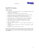
PowerTALK 101 Changing more advanced parameters using PT.EXE 1. Connect a PC serial port set for 9600 baud, 8, N, 1 (or actual port settings if changed from default) to any PowerTALK port using a Laplink serial cable (Tx and Rx swapped). 2. Run either PT98 (PowerTALK 98 for Windows 95/NT GUI) or PT (PowerTALK for Windows 95/NT command line). Only PT will be covered here. PT98 is graphical, and perform similar functions with the known Windows look and feel. 3. To get a list of PT’s capabilities, run “PT.
PowerTALK 101 Passwords Two different passwords are kept on the PowerTALK 101 units. One is variable and can be used for access from a remote network location, and the other fixed but only for access from the local serial port. The password for network access can be changed, and can also be forgotten. The password for local access using the local serial port is fixed, for the eventuality a user forgets his password.
PowerTALK 101 PT.EXE – PowerTALK command line interface The command line interface under W95 DOS or WNT command line, connects to PowerTALK units via the TCP/IP Ethernet port and network. Command line options for PT.EXE are given below: PowerTALK 101 configuration utility version 1.01. Type pt -h for help. Copyright 1998 For distribution with PowerTALK 101 by Cocoon Creations CC. Usage: PT [options] PT [options] password command hst [arguments] hst is the hostname or IP address.
PowerTALK 101 List all available PowerTALK units From a command prompt in Windows 95/98/NT, type: PT –I10.1.1.7 A list will be displayed with the connected PowerTALK units, for this example 10.121.3.85 is the PowerTALK 101 unit assumed to be connected. Set a PowerTALK unit name From a command prompt in Windows 95/98/NT, type: PT –I10.1.1.7 martian hostname 10.121.3.
PowerTALK 101 PowerTALK 98 – Windows GUI software PowerTALK 98 is the 32 bit Windows interface to PowerTALK 101. The Windows software connects to a serial port on PowerTALK 101. PowerTALK 98 is developed to simplify the process of setting up a number of PowerTALK 101 units locally or from remote. PowerTALK 98 requires one serial connection from a PC running Windows 95, 98 or NT to a PowerTALK 101 unit.
PowerTALK 101 PowerTALK 98 examples Double clicking on a selected PowerTALK 101 unit on the main screen results in either of the following screens to pop up. These screens may be used to set up both network and serial port parameters.
PowerTALK 101 Network Topology PowerTALK 101 allows your Ethernet system to be used for control data transport tasks without interfering with normal network operations. The units are 802.3 compliant and use protocols from the TCP/IP suite, so they are fully routable and because they only use Ethernet capacity when carrying data – they have very little affect on network performance.
PowerTALK 101 PowerTALK 101 allows its two ports to be individually linked to any port of any other PowerTALK 101 unit (the above example shows them linked in a one-to-one fashion just for simplicity). You can connect as many PowerTALK units as you wish to your network, obeying normal Ethernet rules, and set up connections between units with complete freedom.
PowerTALK 101 PowerTALK 101 configuration Pre-connect configuration You can make a few minor configuration changes to each unit before you connect them to your network. The most important thing is to give each unit a unique name and or IP number. Each unit has storage for all user configurations and these configurations are reloaded each time the unit is powered up. PowerTALK 101 can be connected to the network in its default configuration.
PowerTALK 101 Network connection: IP address setting In the case of network configuration, the host PC must be configured to be able to speak to the network ports on the PowerTALK 101s. Using Windows NT, one must “add” another IP address to its configuration. Using Windows 95, only one IP address is allowed per PC, forcing the user to change his network settings each time he changes networks form the normal office network to the PowerTALK Ethernet network.
PowerTALK 101 Other settings on PowerTALK 101 Next, using PT.EXE or PT98.EXE, rename each PowerTALK 101 unit to suit your site. You may also change passwords, port settings, IP number, default gateway IP number and subnet mask from this menu. Note that a subnet mask must be defined if the custom IP address is used. Connecting to the physical network The relevant medium must be connected, i.e. a RJ-45 telephone connector in the case of 10Base-T.
PowerTALK 101 Commissioning aids LED indications Normal LED indications on face plate: Refer to the LED description on page 13. All LEDs are scanned through all possible states in sequence red/green, top to bottom, immediately prior to start of operation. • ON/FAIL Green The communications processor card has initialised and is working properly Red An operational error has occurred. This Red is not automatically recovered. The machine must be reset.
PowerTALK 101 Tests Tests using standard networking protocols: • The standard PING program supplied with Windows 95/98/NT can be used to determine network operation, confirming PING time to the specified PowerTALK unit. Tests available using PT.EXE • Networking loopback echo test. A special packet is sent to PowerTALK 101, and a special packet containing address information is returned. Tests available using PowerTALK 98 under Windows 95 or NT • Networking loopback echo test.
PowerTALK 101 Testing procedure It is suggested that a PowerTALK unit or system is laboratory tested prior to shipping to site. A simple, but effective test is described below: Using the default settings on the PowerTALK unit, i.e.: 9600 8N1, with the standard IP addresses, as are indicated on the back of the units. 1. Power up 2 PowerTALK units, confirming that the green “ON” LEDs are on 2. Connect a Server Flylead (Crossed over UTP lead) between the two PowerTALK units 3.
PowerTALK 101 Easy functionality test - Loopback test: A terminal program is used to send a character through a set of PowerTALK units, through the loopback connector, and then echoed back to the terminal program. The complete loop is functional if the echo is visible.
PowerTALK 101 Default settings: 9600 8N1 COM1 Use Windows’ HyperTerminal, connected with a Laplink cable Loopback test connection Port 1 = Ch 1 Port 2 = Ch 2 Port 1 = Ch 1 Port 2 = Ch 2 A B Use the red server flylead to connect Ethernet ports Insert Loopback plug into Serial 1 For the loopback test described above, no setting changes are required. The PowerTALK 101 units can be unpacked from the original boxes, powered up, and immediately be connected to perform above functionality test.
PowerTALK 101 Setting and configuring PowerTALK 101 Default settings: 9600 8N1 Use Windows’ HyperTerminal, connected with a Laplink cable Port 1 = Ch 1 Port 2 = Ch 2 Port 1 = Ch 1 Port 2 = Ch 2 A B Use the red server flylead to connect Ethernet ports Setting and configuration Any PowerTALK 101 unit can be remotely configured from any connected PowerTALK 101 serial port or Ethernet port. In above example, “A” is connected using a serial connection, and “B” is connected using its network port.
PowerTALK 101 Practical connection example – Address type serial devices An address type serial device uses a protocol preventing it from answering to all messages from the master station. The device is given some ID address to which it will respond. The connection below effectively connects device C and D to the same multi-drop network. This connection demands a device that will only respond to its ID call from a master controller.
PowerTALK 101 Practical connection example – Non address (old) type serial devices An address or ID type serial device uses a protocol preventing it from answering to all messages from the master station. The device is given some ID address to which it will respond. A nonaddress or non-ID type device will respond to all message on the serial line, assuming everything is destined for it.
PowerTALK 101 Practical multi node example This example assumes two different types of protocols, not allowed to be on the same physical serial network. It shows each PC COM port to go to a different subnet of address or ID type serial devices, i.e. devices each with an individual address on the subnet. The equivalent logical network is also shown below: All PowerTALK 101s set to: COM1 COM2 COM1, 2 PC Connections: COM1 to Serial1 (Ch. 1) COM2 to Serial2 (Ch.
PowerTALK 101 To the PC master station it appears to be connected to two separate transparent serial links.
PowerTALK 101 Technical detail Settings for popular Siemens & GE Multilin equipment The serial settings for Siemens DIGSI 7SJ600 protection relays are: The serial settings for GE Multilin 239 protection relays are: 11 bit, 9600 8E1 10 bit, 9600 8N1 Channels The concept of channels was introduced to facilitate the selective connection of various PowerTALK units, connected to the same Ethernet network.
PowerTALK 101 Potential PowerTALK lock-ups Endless loop If PowerTALK 101 SERIAL 1 is looped back to SERIAL 2, and both ports are configured on the same channel, an endless loop may occur as follows: ♦ ♦ ♦ ♦ Another PowerTALK 101 on the network on channel n, broadcasts a character The local PowerTALK 101 receives it Channel n receives it from Ethernet It gets delivered to serial port S1, which is connected to channel n • • • • • It gets looped back to serial port S2 via the Laplink cable Serial port S2 is
PowerTALK 101 Testing system watchdog PowerTALK 101 has a watchdog system implemented to guard against hardware and/or firmware failure. It is very difficult to test since one needs an actual faulty processor, but can be simulated by the short, as indicated. The short actually forces the PowerTALK 101 unit to not refresh the watchdog timer, resulting in repeated system reset. Link for Watchdog test LED connector, DB-25F (holes) seen from the outside of the box.
PowerTALK 101 PowerTALK 101 protocol PowerTALK 101 supports the TCP/IP suit of protocols, namely IP, ARP, ICMP and UDP. Presently it will respond to ICMP Ping and ARP, although it cannot originate Ping requests. ARP requests are sent. PowerTALK’s own protocol and the transported data are carried inside UDP datagrams. The data carried is 1 byte minimum (after time out) and128 bytes maximum. The Ethernet encapsulation is as defined in RFC 894 and mandated by RFC 1022.
PowerTALK 101 Other products available in the PowerTALK family PowerTALK 110 Serial data switch Access & configuration from serial port(s), network port REMOTE COMMUNICATION TO MULTIPLE RS-232 LINKS 6, 10, 14, 18 or 22 serial ports. More optionally available. PACKETIZING OF SERIAL DATA STREAM ONTO ETHERNET TCP/IP compatible 2.5kV isolation PowerTALK 120 IP and/or MAC router Access & configuration from serial port, network port 2, 3 or 4 network segments available. TCP/IP compatible 2.
PowerTALK 101 History of changes to this manual, from release 1 Release 2 Small changes are not listed. Added “commit” under PT.
PowerTALK 101 Notes 53
PowerTALK 101 54