FET PREAMPLIFIER 01 OPERATION MANUAL T E C H N O L O G I E S I N C .
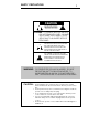
SAFETY PRECAUTIONS 1 CAUTION WARNING ! CAUTION: TO PREVENT ELECTRIC SHOCK, DO NOT REMOVE COVER. NO USER SERVICEABLE PARTS INSIDE, REFER SERVICING TO QUALIFIED SERVICE PERSONNEL. THIS SYMBOL IS TO ALERT YOU OF THE PRESENCE OF UNINSULATED DANGEROUS VOLTAGE WITHIN THE UNIT'S ENCLOSURE THAT MAY BE OF SUFFICIENT MAGNITUDE TO CONSTITUTE A RISK OF ELECTRIC SHOCK. ! THIS SYMBOL IS INTENDED TO ALERT YOU OF THE PRESENCE OF IMPORTANT OPERATING AND MAINTENANCE INSTRUCTIONS IN THE LITERATURE ACCOMPANYING THE UNIT.
INTRODUCTION 2 This preamplifier is a precision device, designed in an effort to provide the listener with unmatched sound quality, design, and construction. In order to operate your preamplifier properly and to realize all of the capabilities of the FET PREAMPLIFIER 01, we recommend that you read this entire manual carefully.
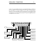
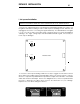
INSTALLATION CONNECTIONS 3 The first section of the installation instructions for the FET PREAMPLIFIER 01 is a diagram of the basic configuration required to bring the preamplifier into an operating mode. These brief steps will allow you to begin operating your system. Make sure during installation that the level control is turned fully counter clockwise, all other components are off, and AC power connections are interrupted to the preamplifier.
DETAILED INSTALLATION 4 I. Set up and Installation WARNING: NEVER OPERATE THIS UNIT WITH THE TOP COVER REMOVED. NEVER MAKE ANY INTERNAL ADJUSTMENTS WHILE THIS UNIT IS CONNECTED TO AN AC POWER SOURCE. 1. If the phono stage has been incorporated in the preamplifier it will be necessary to set the gain as well as the loading for each channel prior to installing the unit. With the unit unplugged, remove the cover using the supplied Allen key.
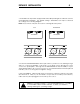
DETAILED INSTALLATION 5 3. The balanced outputs are equipped with switchable phasing due to differences in the USA/EUROPEAN standards. The default setting is EUROPEAN, but may be switched according to the following diagram. Note: These switches may also be used for selecting absolute phase . USA EUROPEAN XLR BOARD XLR BOARD BALANCED OUTPUT LEFT BALANCED OUTPUT RIGHT LEFT _ 2 1 + 3 + 3 1 2 _2 1 RIGHT + _ 3 _ 3 1 +2 4.
DETAILED INSTALLATION 6 II. Source-Output, and Power Connections The input and output connectors are clearly marked on the rear lip of the top cover. It is important to remember the correct left or right channel orientation. The function and channel markings on the rear panel correspond to the front panel controls and their signal paths. 1. The GROUND post should be attached to the ground wire from a turntable. 2.
DETAILED INSTALLATION 7 III. Front Panel Control Functions 1. The INPUT SELECTOR control selects the source which will be presented to the unbalanced OUTPUTS and BALANCED OUTPUTS. 2. The RECORD SELECTOR control selects the source which will be presented to both of the record outputs. Because of the independent controls, one source may be monitored while a second, different source is being recorded.
DESIGN PHILOSOPHY 8 I. Design Philosophy and Approach The circuitry utilized in your FET PREAMPLIFIER 01 is the result of an advanced and complete design process combining innovation and proven fundamentals. This process avoids both the limitations of total adherence to convention and the flaws resulting from inappropriate application of clever circuit gimmicks. Our approach demands painstaking consideration of every facet of each design choice regardless of how small.
DESIGN PHILOSOPHY 9 balanced inputs on many power amplifiers. The most commonly acknowledged advantage of this is rejection of stray noise pickup, but improvements in distortion and bandwidth may occur also. While many manufacturers intentionally omit recording buffers on the grounds of signal path simplification, the potential advantages of their use were worth an investigation.
DESIGN PHILOSOPHY 10 II. Parts' Quality 1. Finishes - All exterior and interior metal parts are anodized. While paint may be more impact resistant, the anodized surface is more resistant to solvents and prevents corrosion. Moreover, the anodized parts' appearance can be enhanced by either graining or bead-blasting the surface. 2. Circuit Boards - Circuit boards are fiberglass epoxy with gold plating over a tin/nickel barrier.
TECHNICAL DATA 11 HIGH LEVEL Frequency Response: Distortion: Gain: Maximum Output: Noise: Input Impedance: Output Impedance: Crosstalk: DC to -3dB @ 200kHz <.01 percent from 10Hz to 40kHz @ 6 Volts peak into 600 Ohms or higher, shunted by 1000pF or less .
CARE and HANDLING 12 The interior of the unit requires no special care, due to the use of sealed controls and gold plating on contacts. If it becomes necessary to clean the exterior, a simple dusting may be all that is required. If a cleaner is necessary, any dilute commercial ammonia based product will be appropriate. NEVER use any abrasive rags, cleaners or chemical solvents on the preamp.
WARRANTY 13 I. Warranty- Any failure of the FET PREAMPLIFIER 01 to operate or to meet specifications, applicable at time of manufacture, due to a manufacturing defect or component failure, will be corrected by Coda Technologies, Inc. without charge for parts, or labor for a period of ten years from date of original purchase. Coda Technologies, Inc. will provide for surface transportation to and from the factory from an authorized Coda Technologies, Inc.
WARRANTY REGISTRATION Fill in and retain this copy of the warranty registration sheet for your records .
WARRANTY REGISTRATION 14.5 Please fill in and send this copy of the warranty registration sheet to Coda Technologies, Inc.
ADDRESS Coda Technologies, Inc.