
User guide


Charnwood Dynamics Ltd. Coda cx1 User Guide – Advanced Topics III - 1
CX1 USER GUIDE - COMPLETE.doc 26/04/04
93/162
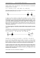
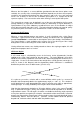
The simplest option is to use the third marker to indicate a direction perpendicular to the
line joining the first two and thereby define a virtual point ‘out-of-line’ but ‘in-plane’. An
intermediate virtual marker may be determined, as shown above, on the line between M
1
and M
2
and then shifted perpendicularly towards M
3
by the distance specified (in mm) in
the first offset box. For this purpose M
3
is given a zero weighting since it merely helps to
define the perpendicular direction.
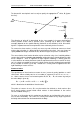
This construction is easily extended to three dimensions using the second offset, X,
normal to the plane of M
1
M
2
M
3
.
Note that the X offset remains valid only while M
1
, M
2
and M
3
remain non-colinear.
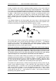
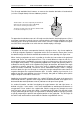
Alternatively, all three markers may be given weights according to the same rules used in
the linear case. Without using offsets the resulting virtual marker would be confined to the
plane of M
1
M
2
M
3
, though not necessarily within the bounds of the triangle since, once
again, the use of negative weighting allows access to the entire plane.
The above diagram corresponds (approximately) with the marker weights: w
1
= -2, w
2
= w
3
= 3, which normalise to -0.5, 0.75, 0.75 respectively. One can see how an intermediate
virtual marker (of weight 1.5) is derived mid-way between M
2
and M
3
. The ‘buoyancy’ of
M
1
then extends the final balance point beyond the bounds of the marker triad to locate
M
V
.
M
M
2
M
V
(in plane of M
1
M
2
M
3
)
offset
L
M
3
(no weight)
intermediate
M
M
2
M
V
(out of plane M
1
M
2
M
3
)
1
st
offset
L
M
3
(no weight)
intermediate
intermediate
X
2
nd
offset
M
M
2
M
V
(in plane of M
1
M
2
M
3
)
M
3
w
1
balance point
intermediate