Coda Audio C3 DSP amplifier User Guide version 1 1
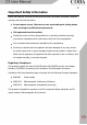
Important Safety Information Please read carefully and keep the following instructions and safety information. Heed all warnings and follow all instructions. Do not remove covers. There are no user serviceable parts inside; please refer servicing to qualified service personnel. This equipment must be earthed. Protect the power cord from being walked on or pinched, particularly at plugs, convenience receptacles and the point where they exit from the apparatus.
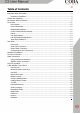
Table of Contents Important Safety Information .................................................................................................. 2 Regulatory Compliance .................................................................................................... 2 Thanks and Unpacking ............................................................................................................ 5 Introduction and Key Features .............................................................................
EQ and Filter Response Graphs .............................................................................................. 25 Signal Processing Block Diagram ........................................................................................ 28 Technical Specifications .....................................................................................................
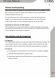
Thanks and Unpacking Thank you for choosing a Coda Audio C3 DSP amplifier system for your application. Please spare a little time to study the contents of this manual, so that you obtain the best possible performance from this unit. All Coda Audio products are carefully engineered for world-class performance and reliability. If you would like further information about this or any other Coda Audio product, please contact us. We look forward to helping you in the near future.
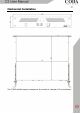
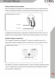
Mechanical Installation The C3 DSP amplifier system is designed to be mounted in a standard 19” rack enclosure.
Where the amplifier is used in a fixed installation, it is possible to use only the front panel 19” rack mounting holes to mount it in a standard rack enclosure. If the amplifier is mounted in a mobile rack it is recommended that the rear rack mounting kit is fitted so the amplifier can be well supported. Damage caused by insufficient support is not covered by the warranty. To prevent damage to the front panel it is recommended that plastic cups or washers are fitted underneath the rack mounting bolt heads.
AC Power Connection WARNING! THIS APPLIANCE MUST BE GROUNDED. The amplifier must always be connected using a 3-wire, grounded AC supply. The framework of the rack mount enclosure should also be connected to the same grounding circuit. The unit should never be operated unless the AC power cable ground is correctly terminated; this is important for personal safety and for control of the system grounding. The amplifier is supplied with a Neutrik PowerConTM type locking AC power connector.
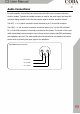
Audio Connections For each amplifier channel there are female and male XLR input connectors which are wired in parallel. Typically the female connector is used for the audio input, the male XLR connector being available to link the same audio signal to another amplifier channel. The HOT, + or „in phase‟ connection should be made to pin 2 of the XLR connector. The COLD, - or „out of phase‟ connection should be made to pin 3 of the XLR connector.
Using unbalanced connections When connecting the C3 amplifier to an unbalanced audio source, the signal conductor should be terminated to XLR pin2 and the cable screen terminated to both pins 1 and 3. Input XLR unbalanced connection 2 1 3 Pin 2 HOT + Pin 1 Shield In bridged mode output channel 1 signal chain provides the signal for the 1 & 2 pair of amplifier channels, output channel 3 signal chain provides the signal for the 3 & 4 pair.
More than one speaker can be connected to each channel provided the total impedance per channel is not less than 2 ohms. In bridged mode the minimum total impedance should not be less than 4 ohms. 100V line operation A single channel of an C3 can deliver 1250W in to 2 Ohms, therefore the RMS voltage at the speaker terminals when delivering this will be √(1,250 x2) = 50V.
Front Panel Power Switch The C3 amplifier is fitted one dual channel power module. When the power switch is operated, the protect indicator will flash while the DSP and amplifier control systems are prepared. After approximately 3-4 seconds the amplifier will be operational and the audio level is gradually ramped up. Power ON indicator The Power Switch is associated with a POWER indicator. This green indicator is lit when power is applied and the power switch is in the ON position.
Protect The C3 DSP amplifier system has sophisticated protection and monitoring systems which keep the amplifier within its safe operating window whenever possible. This indicator lights when the protection systems are active in any way. User DSP indicator Using the C-Net PC application the user can introduce audio processing such as EQ, gain and delay. These settings can be bypassed using the User DSP settings defeat button. The indicator will be lit when these DSP settings are in use.
Rear Panel Power Inlet The C3 amplifier should be connected to a suitable mains electricity supply using the cable supplied. The unit uses auto ranging switch mode power supplies which are capable of operating with a nominal mains voltage of either 115V or 230V, 50/60Hz without reconfiguration. Audio Input Connectors All audio connections are fully balanced and wired pin-1 ground, pin-2 hot & pin-3 cold. The two inputs have pin-1 connected directly to the chassis and feed the signal processing chains.
Or alternatively, if you want to have one cable feeding two speakers, use Speakon 1 pins 1+ and 1- for the first speaker, and pins 2+ and 2- for the second speaker. For Bridge operation, use Speakon 1 pins 1+ and 2+ (1+ for Speaker + and 2+ for speaker -) Communications Port Connections Coda Audio C3 DSP amplifiers may be controlled and monitored using the C-Net PC application.
Cat5 cable. If you are using USB to connect to the C-Net Interface, then the Interface will usually power itself via USB. However, if you are using RS232, or if you are using an unpowered USB hub, or you have some network powered C-Net network equipment in the network, then you will need to use an Accessory Power Supply to power the Interface. The Aux In socket may be used to select between a number of „Voices‟ that may have been programmed into the C3 using factory files (*.dfa) supplied Coda Audio.
This section of the user guide explains the functions of the C-Net control panel for the C3 DSP amplifiers. For further help and information on the main C-Net application please click on the help button on the main application. For more detailed help about the C3 control panel, click the “?” in the right-hand corner of the C3 control panel in C-Net. User Controls The control panel for the DSP amplifier allows the parameters to be viewed and adjusted.
Factory settings determined entirely by the Factory preset file from Coda Audio (called “Factory voice”) – see Loading Factory Presets, or Your own settings (called “User voice”) which overlay these basic factory settings. A recessed Defeat button on the front of the amplifier allows you to select between Factory and User DSP settings. Click the button to toggle between these two modes. When the User DSP indicator is off, the amplifier is in Factory voice.
Adjust the routing from inputs to outputs (allowing you for example to feed two outputs from one input). Regardless of hiding, you will always be able to see the routing in use Control Bridge mode (see Bridge Mode) Adjust the protection limiters (see Limiters). The EQ / Delay tab(s) allows you to adjust the equalization, High-pass and Low-pass filters, and delays.
The Power button allows the amplifier to be put into power saving mode when it is not being used. The associated Auto Power Save Time control allows the amplifier to automatically go into power-save if no audio signal has been detected for a period of time. This function can be defeated by setting the latter control to Manual. We would strongly advise leaving it set to automatic however.
Loading Factory Presets Coda Audio will provide you with one or more „preset library‟ files which contain settings for specific loudspeakers. These take the form of Factory files (Device Factory files (with file extension .dfa)). When you load preset factory settings into this type of device, the current user settings will be preserved since the factory settings will only overwrite the default factory DSP settings rather than the User DSP settings.
Keyboard Shortcuts C-Net supports the following „shortcuts‟: Tab Move to next control In value boxes: CTL+C Copy CTL+V Paste CTL+X Cut CTL+Z Undo On Drop-down, Spin, Push, Fader and radio controls: PgUp Increase value (coarsely) PgDown Reduce value (coarsely) Up/Right arrow Increase value (finely) Down/Left arrow Reduce value (finely) On push-button controls: Space Activate Audio Processing The Digital Signal Processor (DSP) within the amplifier does all the necessary processing (such as
12dB/Octave Linkwitz-Riley 18dB/Octave Bessel 18dB/Octave Butterworth 24dB/Octave Bessel 24dB/Octave Butterworth 24dB/Octave Linkwitz-Riley A 2nd order low-shelf filter with frequency variable over the range 10Hz to 25kHz, and boost/cut from –15 to +15dB, and slope from 6 to 12dB/Octave. A 2nd order high-shelf filter with frequency variable over the range 10Hz to 25kHz, and boost/cut from –15 to +15dB, and slope from 6 to 12dB/Octave.
Bridge Mode When the amplifier is set to Bridge Mode, it uses two amplifier channels to drive one loudspeaker with greater power. In this mode, there is only one set of Output controls per of amplifier. Protection Comprehensive protection features preserve the longevity of the loudspeaker and amplifier by continuously monitoring several critical parameters, and reducing the gain, or muting the amplifier either temporarily or permanently depending on the nature and seriousness of the fault or misuse.
EQ and Filter Response Graphs The following plots show the attenuation characteristics of the various crossover filters available within the C3. These are all shown at a crossover frequency of 1kHz.
Bessel 6 Magnitude, dB 0 6 12 18 24 30 36 100 3 1 10 Frequency, H z 4 1 10 12dB/Oct 24dB/Oct Hardman 6 Magnitude, dB 0 6 12 18 24 30 36 100 3 1 10 Frequency, H z 4th Order 8th Order 26 4 1 10
The following plots show the magnitude response (frequency response) characteristics of the various equalization filters available within the C3. These are all shown at a c frequency of 1kHz.
Signal Processing Block Diagram Please note that each C3 contains one of these processing blocks.
Technical Specifications AUDIO Input impedance 10k balanced Max Input level +20dBu Frequency Response 20Hz - 20kHz+/-0.5dB @ 4 Ohm load Output noise -106dB A weighted Ref max output, 22kHz BW Distortion <0.05% (1kHz, -3dB output.
POWER SUPPLIES Type High current, high freq.
This product complies with the EMC & LVD directives as issued by the Commission of the European Community. Compliance with these directives implies conformity with the following European standards: EN55103-1 Electromagnetic Interference (Emission) EN55103-2 Electromagnetic Susceptibility (Immunity) EN60065 Electrical safety C3 also meets the requirements of FCC part 15B.