
Manual

INSTALLATION & USE 3
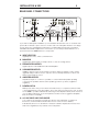
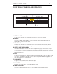
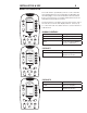
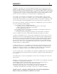
REAR PANEL CONNECTIONS
To provide for adequate ventilation you should allow at least six inches of unobstructed
space above and a couple of inches on each side of the amplifier. Because of its large
power supply, a local magnetic field may be created and picked up by CD players,
turntables and similar equipment. For this reason you should provide at least a foot of
space between the CSib and these components.
A. INPUT SELECTOR
Signal inputs for Disc, Video, Aux and Aux2.
B. MONITOR
Signal inputs and outputs for a tape deck or other recording device.
C. PREAMPLIFIER OUTPUTS
Signal outputs for an additional outboard amplifier.
D. SUBWOOFER OUTPUTS
Variable outputs for a powered subwoofer which track the master volume. Future
upgrades will provide for these 2 outputs to be used independently for Subwoofer
and Center Channel control
E. AMPLIFIER OUTPUTS
Amplified outputs to connect to speakers. To ensure identical speaker phasing
connect both speakers with the same polarity (positive to positive, negative to
negative).
F. POWER SWITCH
Main power switch. This power switch is intended only for complete shutdown while
connecting and disconnecting cables. The rocker switch must be in the “ON” position
for the CSib to operate. Rather than switching off the amplifier entirely when it is not in
use, the bias pushbutton on the front panel should be used to toggle the amplifiers
bias off when it is in standby.
G. AC LINE INPUT AND FUSE HOLDER
110 or 220 volt power input, fused as specified on the rear panel. To replace a
blown fuse, insert a small screwdriver into the slot next to the fuse drawer,
indicated by a fuse icon, and twist to release the drawer. Replacement fuses must
match the original fuse as specified on the rear panel.
~
MAIN POWER
AUX1
VIDEO
AUX2
BALANCED
120
C&D A
B
G
F E