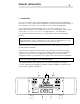
Amplifier S12.5 OPERATION MANUAL T E C H N O L O G I E S I N C . XLR/GN BIAS PRECISION BIAS CLASS A AMPLIFIER S INPUT LEFT RIGHT RCA/YL 12.
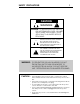
SAFETY PRECAUTIONS 1 CAUTION WARNING ! CAUTION: TO PREVENT ELECTRIC SHOCK, DO NOT REMOVE COVER. NO USER SERVICEABLE PARTS INSIDE, REFER SERVICING TO QUALIFIED SERVICE PERSONNEL. THIS SYMBOL IS TO ALERT YOU OF THE PRESENCE OF UNINSULATED DANGEROUS VOLTAGE WITHIN THE UNIT'S ENCLOSURE THAT MAY BE OF SUFFICIENT MAGNITUDE TO CONSTITUTE A RISK OF ELECTRIC SHOCK. ! THIS SYMBOL IS INTENDED TO ALERT YOU OF THE PRESENCE OF IMPORTANT OPERATING AND MAINTENANCE INSTRUCTIONS IN THE LITERATURE ACCOMPANYING THE UNIT.
INTRODUCTION 2 Thank you for purchasing the AMPLIFIER S12.5. This amplifier is a precision device, designed in an effort to provide the listener with unmatched sound quality through superb design and construction. Although its operation is fairly simple, in order to operate your amplifier properly and to realize all of the capabilites of the S12.5 we recommend that you read this entire manual carefully.
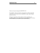
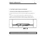
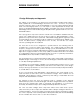
INITIAL SETUP 3 WARNING: Please ensure that the power switch is turned OFF while you are connecting the amplifier. Connecting or disconnecting cables while the amplifier is powered on could cause damage to your speakers. The diagram below shows the default connections necessary to operate the AMPLIFIER S5.5 as a stereo amplifier. This is the simplest and most common mode of operation, and the quickest way to get started.
DETAILED INSTALLATION 4 I. Connections The connectors and controls are clearly marked on the back panel of the AMPLIFIER. Note the correct left or right channel orientation. The function and channel markings on the rear panel correspond to the front panel controls and their signal paths. 1.The UNBALANCED and BALANCED inputs should be attached to the appropriate unbalanced and balanced outputs of a preamplfier either directly or through a crossover or processor, as appropriate to the application. 2.
DETAILED INSTALLATION 5 II. Front Panel Control Functions and Indicators 1. The BIAS button enables the bias, effectively "turning on" the amplifier's components, and opens shunting relays that mute the input. 2. The INPUT SELECTOR button switches between the balanced and unbalanced inputs. 3. These LEDs, when lit, indicate that the bias is enabled and muting is off. 4. This two color LED indicates that the main power is on. When it is red the balanced inputs are in use.
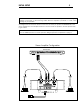
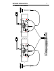
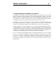
DETAILED INSTALLATION 6 III. BRIDGED SETUP WARNING: Disconnect the amplifier's power cord from the AC supply and set the power switch to OFF before adjusting the mode switch or connecting or disconnecting any cables to avoid potential damage to your speakers. The S12.5 normally operates in stereo mode, providing a maximum output power of 50 watts Class A (into an 8-ohm load) per channel. In BRIDGED mode, both channels act as one amplifier providing a maximum output power of 200 watts.
7 DETAILED INSTALLATION IV. BRIDGED SETUP DIAGRAM LEFT SPEAKER Bridged Output LEFT CHANNEL INPUTS I UNBALANCED G BALANCED O E S I N C PUSH . STEREO MODE BRIDGED PUSH FUSE AND VOLTAGE SELECTOR 12 0 FUSE VALUE -SEE FUSE CHART VOLTAGE SELECTIONSEE OPERATION MANUAL OFF MANUFACTURED IN THE USA INPUTS BALANCED UNBALANCED CAUTION WARNING ! ! TO ANY ACTIVE CURRENT SOURCE.
DESIGN PHILOSOPHY 8 I. Design Philosophy and Approach The subtlety of the design process at this level of performance makes it impossible to easily explain all of the advantages inherent in the S12.5. However, we present here an overview to give you an understanding of some of its unique features and an idea of the listening experience you can expect. Often a particular technique has numerous unrelated advantages and possibilities.
DESIGN PHILOSOPHY 9 I. Design Philosophy and Approach (continued) To maintain “Precision Bias” requires an advanced bias circuit that must have a very high degree of stability under a wide range of temperatures and load conditions. The usual bias network is of such high impedance and poor thermal regulation that at the extremes of operation, bias currents are ineffectively controlled. Advanced tracking techniques results in absolute control of bias currents under all conditions in the S12.5.
DESIGN PHILOSOPHY 10 II. Material Quality The amplifier’s chassis is made from heavy-gauge steel with a half-inch machined aluminum faceplate. All exterior metal parts are anodized or powder coated for durability. Printed circuit boards are fiberglass epoxy with gold plating over a tin/nickel barrier. The gold layer will not corrode, while the barrier layer prevents the gold from migrating to the lower copper layer.
11 TECHNICAL DATA STEREO Rated Power: Frequency Response: Distortion: Gain: Maximum Current: Noise: input Impedance: Output Impedance: 125 Watts @ 8 Ohms DC to -3dB @ 100kHz < .03 percent from 10Hz to 20kHz @ 125 Watts 26dB >100 Amperes peak per channel -120dB referenced to rated output 50k Ohms unbalanced/1k Ohms balanced .
CARE AND HANDLING 12 The interior of the amplifier requires no special care. If exterior cleaning beyond simple dusting is required, any dilute ammonia-based product is recommended. Do not use any abrasive rags, cleaners or chemical solvents on the amplifier. When handling the amplifier, take care not to mar the faceplate. Aluminum is a medium hardness metal and can be scratched by harder tool steels, and the grained surface can be easily marred if the amplifier is set face-down on a hard surface.
WARRANTY & DISCLAIMER 13 i. Warranty - Any failure of the Amplifier S12.5, hereafter known as the product or original product, to operate or to meet specifications, applicable at time of manufacture, due to a manufacturing defect or component failure, will be corrected by Coda Technologies without charge for parts or labor, for a period of ten years from date of original purchase.
WARRANTY REGISTRATION 14 Fill in this registration sheet and fax or mail it to Coda Technologies to ensure you are in our warranty system. This will facilitate warranty service should it become necessary. It is recommended that you retain a copy of this form for your own records. Coda Technologies’ address and fax number are located on the back of this manual.
7850 CUCAMONGA AVENUE #34 SACRAMENTO, CA 95826 USA T E C H N O L O G I E S I N C . phone +01 916.383.3653 fax +01 916.455.3653 on the web at CODA.CC email us at info@coda.