
User's Guide
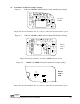


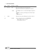
Table Of Contents
DANIELS
ELECTRONICS LTD
TM
4-10 CI-PM-3 Paging Modulator Instruction Manual
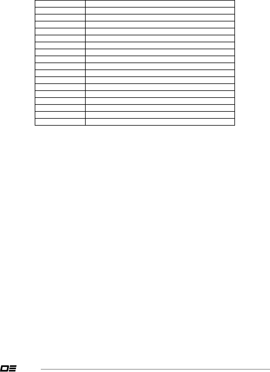
4.10 CI-PM-3 Test Points
Table 4-10 CI-PM-3 Test Points
TEST POINT DESCRIPTION
TP1 +8 Vdc Supply
TP2 +4 Vdc Supply
TP3 +5 Vdc Supply
TP4 Analog / Digital Mode (High = Digital, Low = Analog)
TP5 2 Level Data (TTL)
TP6 OCXO 9.5 Vdc Supply
TP7 Positive and Negative Edge Integrator Output
TP8 Data Delay Programmable Counter Output.
TP9 Input to Data Delay Circuitry
TP10 2 Level Data
TP11 Level Adjusted Paging Signal
TP12 OCXO Reference Adjust (nominally 2.5 Vdc)
TP13 PLL Correction Voltage
TP14 Tx A/B Direct Modulation Output
TP15 13.8 Vdc Supply Input (from Subrack)
TP16 9.5 VDC Supply Input (from Subrack)
TP17 Low Pass Filter Output