
User's Guide


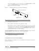
Table Of Contents

DE
DANIELS
ELECTRONICS
3-4 Transmitter Main Board Instruction Manual
• Jumper JU11: not installed Balanced input to auxiliary audio circuit enable.
• Jumper JU12: not installed Tone/Digital input to auxiliary audio circuit enable.
• Jumper JU13: not installed Direct modulation input to auxiliary audio circuit enable.
• Jumper JU14: not installed Auxiliary input preemphasis response enable.
• Jumper JU15: not installed Auxiliary input flat audio response enable.
• Jumper JU16: not installed Subtone input 2 audio path select.
• Jumper JU17: installed MT-2 Temperature compensation bypass.
• Jumper JU18: not installed Continuous data mode selection.
• Jumper JU19: 'y'position Power source for audio switches.
• Jumper JU20 to JU22: not used
• Jumper JU23: not installed Direct modulation input to subtone 2 enable.
• Jumper JU24: installed Lowpass filter response select.
• Jumper JU25: installed Lowpass filter response select.
• Jumper JU26: installed Lowpass filter response select.
• Jumper JU27: not installed Direct Modulation input audio path select.
• Jumper JU28: not installed Amplified direct modulation bypass.
• Jumper JU29: not installed Amplified direct modulation input DC couple enable.
• Jumper JU30: not installed Amplified direct modulation audio path select.
• Jumper JU31: not installed Subtone 2, AC coupled,to direct modulation output enable.
• Jumper JU32: not installed Audio output AC coupled (MT-3 crystal transmitters).
• Jumper JU33: not installed Audio output AC coupled (MT-3 synthesized transmitters).
• Jumper JU34: not installed Audio output from Direct Modulation circuits select.
• Jumper JU35: not installed Direct Modulation output source select.
• Jumper JU36: 'x' position Subtone input 1 audio path select.
• Jumper JU37: not installed Summed Subtone audio to direct modulation output enable
• Jumper JU38: not installed Subtone 2, DC coupled, to direct modulation output select.
• Jumper JU39: not installed Direct Modulation low input impedance enable.
3.6 MT-3 Transmitter Board Alignment
3.6.1 General
Before proceeding with the transmitter alignment, check that the appropriate jumpers are installed.
The standard jumper configuration for the Transmitter Main Board, given in section 3.5.1, is
normally employed for transmitter alignment. In a standard configuration, the only alignment
required on the MT-3 Transmitter Main Board for a synthesized transmitter is to set the frequency
switches (FSW1, FSW2, FSW3, and FSW4) for the desired channel frequency. FSW1 is the
most significant digit of the frequency switches. The switch settings for the desired channel
frequency can be found in the channel designation tables. If the transmitter is using a crystal
control oscillator module, the switch settings are irrelevant.