
User's Guide
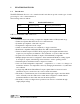

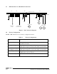

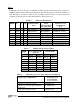


Table Of Contents
1-4 Audio Processor Board Instruction Manual
1.3 FM Audio Processor Board Pin Connections
Figure 2 Pin Connection Diagram
1.4 Factory Configuration
The MT-3 FM Audio Processor is factory configured as follows:
Table 2 Factory Configuration
Parameter Specification
Maximum Deviation
±
2.5 kHz (Narrowband),
±
5.0 kHz (Wideband).
Microphone Input 1 kHz signal at -10 dBm gives
±
60% rated system deviation
1 kHz signal compression set at
±
84% rated system deviation
Audio Balanced Input
pre-emphasis response
1 kHz tone at -8 dBm gives
±
60% rated system deviation
1 kHz signal compression set at
±
84% rated system deviation
Subtone Input 1 100 Hz tone at -18 dBm gives
±
500 Hz (Wideband)
±
350 Hz (Narrowband) deviation
All other audio inputs Disabled
P
CB
1
2
3
4
1
2
3
4
1
2
3
4
1
2
3
4
P1
P2
P4
P3
Ba
l
an
c
ed Input
E
ND V
IEW
M
i
c Input
S
ubtone Inpu
t 1
+
8V
+
9.5
V
Lo
w Fr
equen
c
y
D
i
r
e
c
t Mod
O
utput
Vo
i
c
e
An
d Subtone
O
utput
-
8
d
B
m
-
10
d
B
m
-
18
d
B
m
Su
r
fa
c
e Mount Side
0
d
B
m