
User Manual


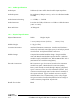

Table Of Contents
- 1GENERAL
- 1.1Introduction
- 1.2Manual Organization
- 1.3UT-4B 406 - 470 MHz Transmitter Family Models
- 1.4Performance Specifications
- 1.4.1General
- 1.4.2Audio Specifications
- 1.4.3Physical Specifications
- 2THEORY OF OPERATION
- 2.1Transmitter Operation
- 2.2Transmitter Programming
- 2.2.1Transmitter Wide Options
- 2.2.1.1Disable Front Panel Led
- 2.2.1.2Secure Hardware Equipped
- 2.2.1.3Allow Emergency Transmissions
- 2.2.1.4Allow Radio Inhibit
- 2.2.1.5Allow Radio Check
- 2.2.1.6Enable Status
- 2.2.1.7Frequency Band
- 2.2.2Channel Wide Settings
- 2.2.2.1Frequency
- 2.2.2.2Voice/Signal Type
- 2.2.2.3Squelch Type
- 2.2.2.4CTCSS Tone
- 2.2.2.5Enable Reverse Burst
- 2.2.2.6DCS Code
- 2.2.2.7DCS Invert
- 2.2.2.8Enable Turn Off Code
- 2.2.2.9Transmitter Power
- 2.2.2.10Channel Bandwidth
- 2.2.2.11Deviation
- 2.2.2.12Time Out Timer
- 2.2.2.13Channel Status
- 2.2.2.14Transmitter Pre-emphasis
- 2.2.2.15NAC Transmitter Code
- 2.2.2.16NAC Transmitter
- 2.3Transmitter Programming using Motorola Radio Service Software
- 2.4Secure Communications
- 2.5Transmitter Assembly and Adjustment
- 2.5.1Controller Board Alignment
- 2.5.1.1Reference Oscillator Adjustment
- 2.5.1.2Transmitter Deviation Balance Adjustment
- 2.5.1.3Transmitter Deviation Limit Adjustment
- 2.5.2Amplifier Alignment
- 2.5.3Frequency Change
- 2.6Recommended Test Equipment List
- 2.7Repair Note
- 2.8Printed Circuitboard Numbering Convention
- 3ILLUSTRATIONS
- 3.1Digital Base Transmitter Front Panel
- 3.2Digital Base Transmitter Case - Exploded View
- 3.3Digital Base Transmitter Block Diagram
- 3.4Digital Base Transmitter Schematic Diagram
- 3.5Digital Base Transmitter Main Board Component Layout (Bottom)
- 3.6Digital Base Transmitter Main Board Component Layout (Top)
- 4PARTS LIST
- 4.1Base Transmitter Main Board Parts List
- 4.1.1Base Transmitter Main Board Electrical Parts List
- 4.1.2P25 Base Transmitter Mechanical Parts List
- 5REVISION HISTORY

DE
DANIELS
ELECTRONICS
1-2 UT-4B400 P25 Di
gital
UHF Base
Transmitter
Instruction
Manual
1.4
Performance Specifications
1.4.1
General
The following is a general set of specifications for the generic UT-4B400 transmitter. Additional
specifications, specific to individual modules may be found in their respective sub manuals.
Type:
MT-4 Series Transmitter.
Family:
UT-4B 406 - 470 MHz.
Compatibility:
MT-2 Series and MT-3 Series Radio Systems, Project 25
interoperable.
Frequency Range:
406 to 430 MHz., 450 to 470 MHz
RF Power Output:
2.0 to 8.0 W Continuous.
Modulation:
Analog:
11K0F3E or 16K0F3E (Frequency Modulation).
Project 25:
8K10F1E
System Impedance:
50 Ω; Type N connector.
Duty Cycle:
100%; Continuous operation from -30°C to +60°C.
Emissions: -66 dBw
Transmitter Mismatch Protection:
20:1 VSWR at all phase angles.
Operating Temperature Range:
-30˚C to +60˚C, optional -40˚C temperature
test.
Operating Humidity:
95% RH (non-condensing) at +25°C.
Operating Voltage:
+13.8 Vdc Nominal (range +11 to +16 Vdc),
+9.5 Vdc Regulated.
Transmit Current:
1.7 Amps at 2 Watts RF Power Output,
2.8 Amps at 8 Watts RF Power Output
Front Panel Controls:
N
ORM (repeat mode), OFF, and KEY TX (Tx on).
PTT Activation:
• Active to ground;
• Microphone activated;
• Front Panel switch:
KEY TX;
PTT Time-Out-Timer:
Programmable from 1 sec. to 8 hrs. (default 5 min.), using
Radio Programming Software package.
Channel Spacing:
12.5 kHz /15 kHz or 25 kHz / 30 kHz.