
Instruction Manual


DE
DANIELS
ELECTRONICS
3-2 MT-3 AM Transmitter Main Board Instruction Manual
Radio communications test set : Marconi Instruments 2955R
VSWR 3:1 mismatch load: JFW 50T-035-3.0:1
Alignment Tool: Johanson 4192
It is recommended that the radio communications test set be frequency locked to an external
reference (WWVH, GPS, Loran C) so that the high stability oscillator may be accurately set to
within its ±1 ppm frequency tolerance.
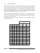
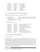
3.5 Standard Factory Settings and Jumper Configuration
Standard factory settings and the associated jumper configuration for each module of the
MT-3 AM series transmitter are given below.
3.5.1 MT-3 AM Transmitter Board Factory Configuration
The MT-3 AM Transmitter Main Board is factory configured as follows:
• Transmitter standby mode 3
• Optional relay not installed.
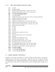
The corresponding jumper settings are:
•Jumper J2: 'x' position Optional relay configuration
•Jumper J3: not installed Optional relay configuration
•Jumper J4: 'y' position Optional relay configuration
•Jumper J6: installed Transmitter standby mode select - Mode 3
•Jumper J7: 'x' position Audio processor standby mode select
•Jumper J9: not installed Receiver audio ac/dc input coupling
•Jumper J12: not installed Not applicable
•Jumper J13: not installed Not applicable
•Jumper J14: not installed Not applicable
•Jumper J15: not installed Not applicable
•Jumper J16: 'x' position Microphone configuration
•Jumper J17: installed Microphone output line
•Jumper J18: 'y' position Synthesizer or crystal module standby mode select
•Jumper J19: 'x' position 600Ω audio transformer bypass
•Jumper J20: 'x' position 600Ω audio transformer bypass
•Jumper J21: not installed +8 Vdc audio processor supply bypass
•Jumper J22: 'x' position 600Ω audio transformer bypass
•Jumper J23: 'x' position 600Ω audio transformer bypass
•Jumper J24: not installed Not applicable
•Jumper J25: 'y' position AM Modulation mode
•Jumper J26: installed TOT configuration