
Instruction Manual


DE
DANIELS
ELECTRONICS
MT-3 AM Transmitter Main Board Instruction Manual 3-3
•Jumper J27: not installed TOT configuration
•Jumper J28: not installed TOT configuration
•Jumper J29: installed TOT configuration
•Jumper J31: installed TOT configuration
•Jumper J32: not installed TOT configuration
•Jumper J33: installed TOT input
•Jumper J34: installed TOT power supply
•Jumper J35: installed TOT output
3.5.2 MT-3 AM Audio Processor Factory Configuration
The MT-3 AM Tx Audio Processor is factory configured as follows:
•Microphone Input: 1kHz tone at -10 dBm gives 50% maximum modulations.
•Audio Balanced Input: 1 kHz tone at -8 dBm gives 90% maximum modulations.
•Automatic Modulation Control enabled
•Automatic Level Control enabled
The corresponding jumper settings are:
•Jumper JU1: 'y' position Automatic Modulation Control enabled
•Jumper JU2: not installed Modulation configuration
•Jumper JU3: 'y' position Automatic Level Control enabled
•Jumper JU4: not installed Time-out-time power supply (optional)
•Jumper JU5: 'y' position Voice application
•Jumper JU6: 'y' position Voice application
•Jumper JU7: not installed Modulation configuration
•Jumper JU8: 'y' position Automatic Level Control enabled
•Jumper JU9: installed Power AMC and Microphone enabled
3. 6 MT-3 AM Transmitter Board Alignment
3.6.1 General
Before proceeding with the transmitter alignment, check that the appropriate jumpers are installed.
The standard jumper configuration for the Transmitter Main Board, given in section 3.4.1, is
normally employed for transmitter alignment. In a standard configuration, the only alignment
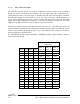
required on the MT-3 AM Transmitter Main Board for a synthesized transmitter is to set the
frequency switches (FSW1, FSW2, FSW3, and FSW4) for the desired channel frequency. FSW1
is the most significant digit of the frequency switches. The switch settings for the desired channel
frequency can be found in the channel designation tables. If the transmitter is using a crystal
control module, the switch settings are irrelevant.